
Stretchable interconnects for flexible electronic surfaces

a flexible, interconnecting technology, applied in the direction of soldering apparatus, manufacturing tools, printed circuit non-printed electric components association, etc., can solve the problems of insufficient resistance of conductive pastes to environmental effects, inability to adapt to selective structuring of existing conductive pastes, and inability to adapt to selective structuring

Active Publication Date: 2020-06-02
FRY S METALS INC
View PDF21 Cites 0 Cited by
  • Summary
  • Abstract
  • Description
  • Claims
  • Application Information

AI Technical Summary

Benefits of technology

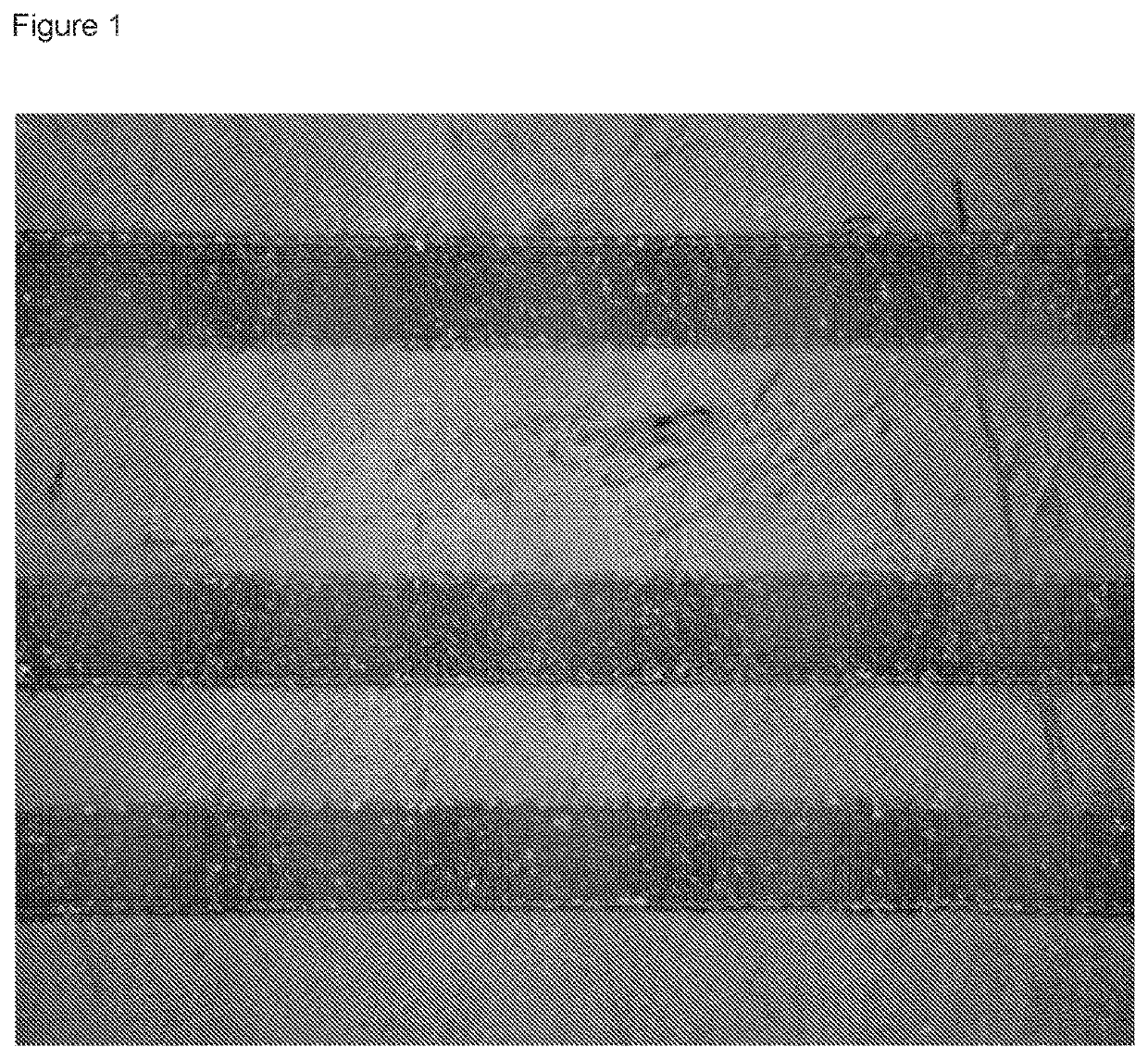
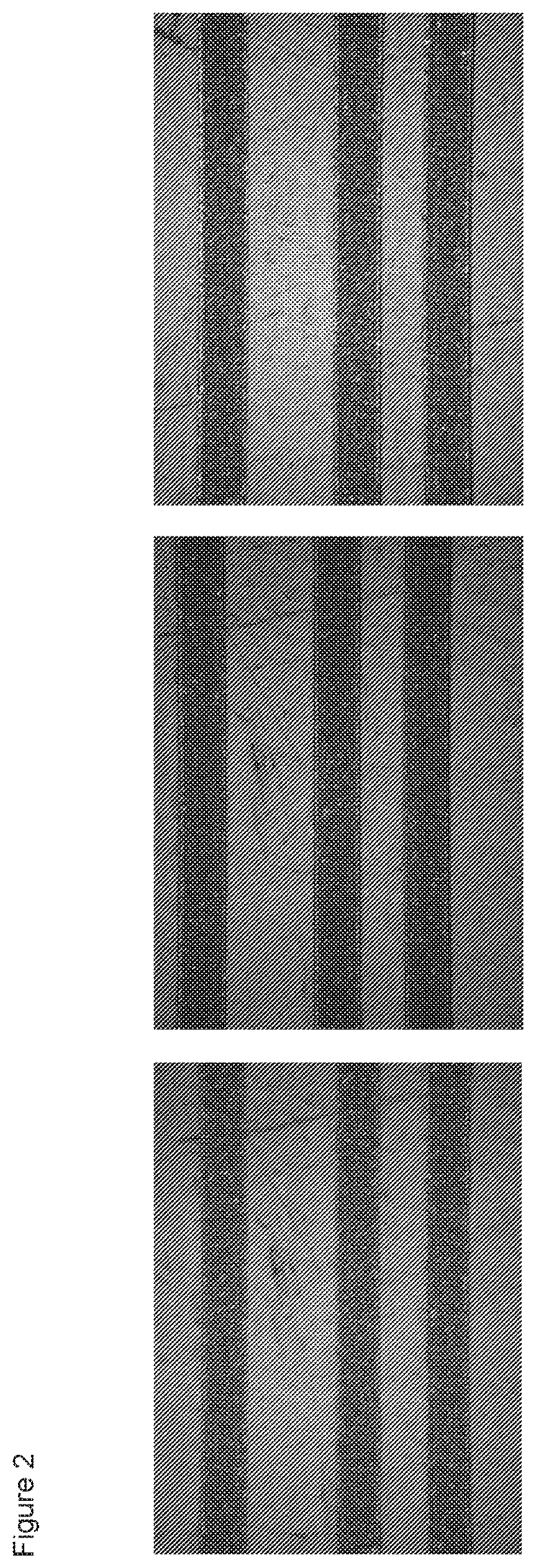
[0019]The inventors have surprisingly found that the conductive paste of the present invention may form a conductive coating / layer, circuit wire or interconnection capable of being stretched (typically up to 150%) without substantial crack formation or substantial loss in electrical continuity. The conductive coating or interconnection may also exhibit excellent volume resistivity, typically of the order of 10−5 ohm-cm. In view of these properties, the conductive paste of the present invention may be used to fabricate low voltage circuitry, especially on flexible substrates. Accordingly, the conductive paste may be particularly suitable for use in capacitive touch technologies and stretchable electronic surfaces.
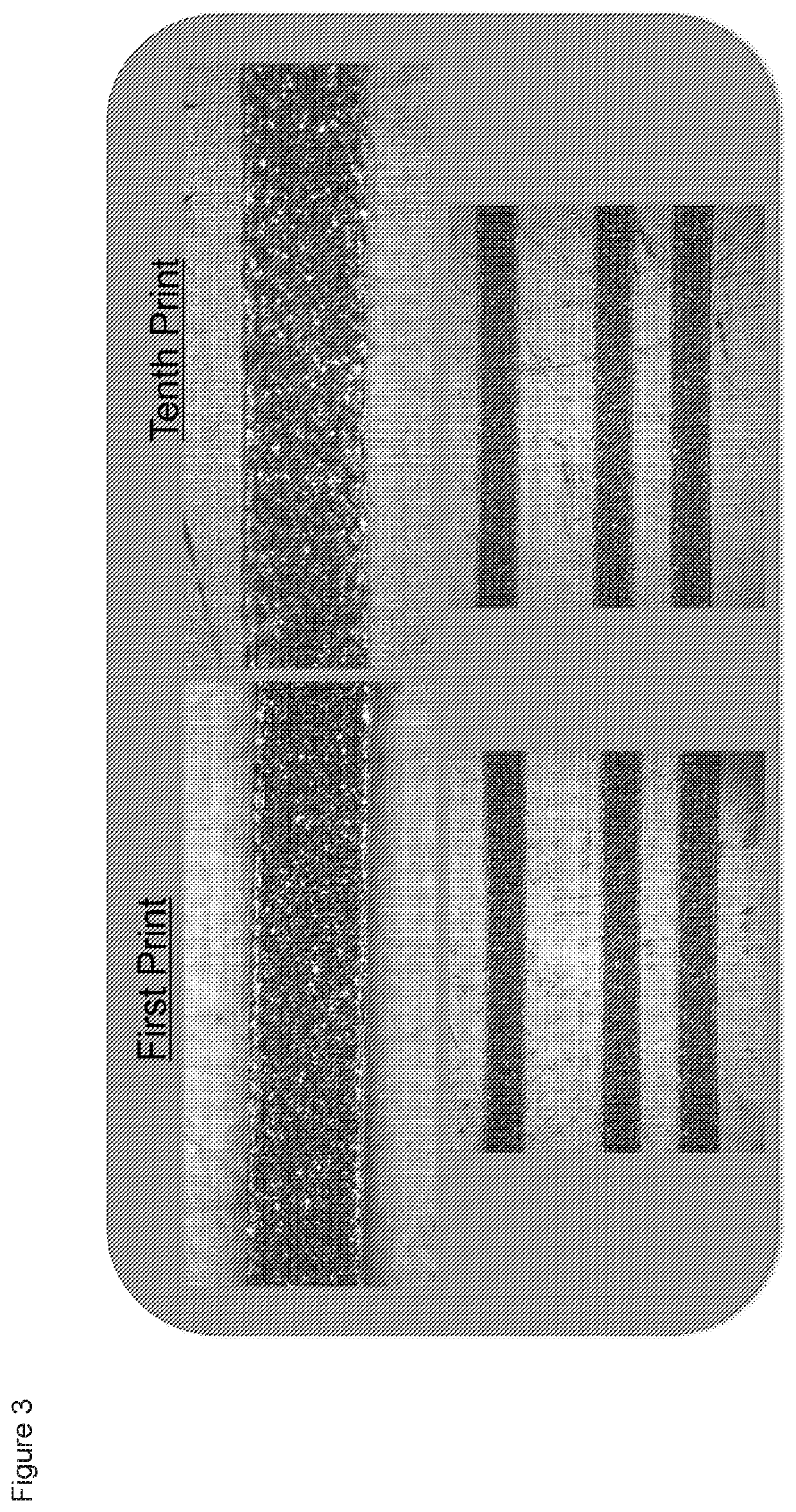
[0020]The conductive paste may be cured at low temperatures at a rapid rate, for example at 65° C. for 20 minutes, and may therefore be particularly suitable for use by manufacturers with limited curing capacity. The conductive paste may also be screen printable, stencil printable and / or jettable, and may be capable of continuous printing without flooding.
[0021]The conductive paste may exhibit excellent adhesion on substrates such as, for example, paper-phenolic resin boards, plastic boards (PMMA, PET or the like) and glass-epoxy resin boards. It is also stable at room temperature, typically for more than one year.
[0022]In comparison to prior art conductive pastes, the conductive paste of the present invention may exhibit improved compressive strength, diametral tensile strength and / or flexural strength. The conductive paste may be capable of being printed in very fine lines, for examples lines of 50 microns or less in width.
[0024]The conductive paste of the present invention may be used to form an electronic surface. Such electronic surfaces may be conformable skin-like structures with large surface area, high mechanical flexibility and even stretchability, and multifunctional capabilities. Such structures may enable electro-active surfaces of arbitrary shape wrapped over airplane wings, buildings, robots, three-dimensional (3-D) displays, and human medical prostheses. One of the most difficult challenges in the development of stretchable electronics is the simultaneous achievement of both excellent mechanical robustness and electronic performance. The conductive pastes can be used for a variety of applications including: LED lighting luminaire fabrication with integrated thermal and electrical interconnect at very low cost, strain absorbing interconnects for high thermal cycle fatigue resistance, robotic sensory skins and wearable communication devices and bio-integrated devices. The conductive pates can be used for high CTE mismatch applications such as, for example, direct chip on board heat sink die attach for LED.
[0026]The conductive paste may act as a cold solder or a conductive adhesive. The paste forms electrical and thermal interconnects that are super elastic and compliant for a variety of applications (including: LED lighting luminaire LED assembly, 3-D in mould labelling etc.) with integrated thermal and electrical interconnect at very low cost. Further, the paste may be used as strain absorbing interconnects for high thermal cycle fatigue resistance, robotic sensory skins, wearable communication devices and bio-integrated devices. The conductive adhesives can be used for high CTE mismatch applications such as, for example, direct chip on board heat sink die attach for LED. The conductive adhesive may be used for PV ribbon attach to Si cells.

Problems solved by technology

Because of this, capacitive displays can be controlled with very light touches of a finger and generally cannot be used with a mechanical stylus or a gloved hand.
The flexibility of the circuit is typically limited not only by the flexibility of the substrate, but also by the flexibility of the electronic devices, circuit lines and interconnections mounted on the substrate.
Existing conductive pastes are not suitable for selective structuring at the micron-sized level, as required, for example, in microelectronics manufacture.
In addition, such pastes do not exhibit adequate resistance to environmental effects such as, for example, extremes of temperature.
In such pastes, the hardening agent is flaky and hard, a therefore the pastes are not suitable for manufacturing flexible circuits.
The electrically conductive pastes are also prone to form a gel after being kept in storage for a long time.
Other conventional polymeric pastes have the disadvantage of non-flexibility.
As a result, a functional circuit made of conventional electrically conductive paste is likely to crack.
Accordingly, when a circuit or conductive layer or interconnection is formed on a substrate using such conventional pastes, damage to the substrate may occur.

Method used


Image

  • Stretchable interconnects for flexible electronic surfaces
  • Stretchable interconnects for flexible electronic surfaces
  • Stretchable interconnects for flexible electronic surfaces

Examples


example 1

[0115]An organic medium for the composition of the invention was prepared as follows: to 170 grams of magnetically stirred carbitol acetate (boiling point 230° C.) and 40 g downol EPI-1 (from Dow Chemicals) were added 15 grams of Dynapol L411 (a linear aromatic polyester resin). Rheology modifier and adhesion promoter were added to the mixture. The mixture was heated to 60° C. and stirred at this temperature until a clear solution was obtained (after approximately 4 hours). The solution was allowed to cool slowly to ambient temperature.

[0116]To the above mixture, 650 parts by weight (65% by weight) of a flaky silver powder with predominant particle size in the range from about 1 to 20 microns and an average major particle diameter of 5 μm blended and dispersed uniformly by a mixing and grinding machine to obtain an electro conductive paste.

[0117]The viscosity of the resultant paste after 24 hour ambient temperature rest measured about 18,000 centipoise (at 20° C.) on a Brookfield RV...

example 2

[0119]An electro conductive paste was obtained by following the same process as in Example 1 except that following flux composition was used:

[0120]

Ingredients:Part by weight:Silver flakes65Carbitol acetate-solvent18.00Downol-solvent4.00Dynapol L411-binder1.30Setal VS60 (trademark of Nuplex)-08.60binderRheology modifier2.50Adhesion promoter0.60

[0121]This composition contained polyester polyol.

example 3

[0122]An electro conductive paste was obtained by following the same process as in Example 1 except that following flux composition was used:

[0123]

Ag flakes65.00Carbitol acetate18.90Thinner3.2Dynapol 4112.60Setal_US_136_BB_1577.20(Trademark of Nuplex)Rheology modifier3.10

[0124]This composition contained branched polyester and polyamine curing agent


PUM

PropertyMeasurementUnit
temperatureaaaaaaaaaa
widthaaaaaaaaaa

Abstract

A conductive paste and method of manufacturing thereof. The conductive paste comprises conductive particles dispersed in an organic medium, the organic medium comprising: (a) a solvent; and (b) a binder comprising a polyester. The conductive paste typically comprises silver and may contain various other additives. A stretchable conductive layer can be formed by curing the conductive paste.

Description

FIELD OF THE INVENTION[0001]The invention relates to a conductive paste and method of manufacturing thereof. The conductive paste may form a conductive coating, circuit wiring or interconnection capable of being stretched without substantial crack formation or substantial loss in electrical continuity, and may therefore find use in capacitive touch technologies and stretchable electronic surfaces. The solderable version of this paste can be used directly in joining two metal surfaces.BACKGROUND OF THE INVENTION[0002]Capacitive touchscreen displays, for example those present in smart phones, rely on the electrical properties of the human body to detect when and where on a display the user is touching. Because of this, capacitive displays can be controlled with very light touches of a finger and generally cannot be used with a mechanical stylus or a gloved hand. For a capacitive device, the capacitive screen is made of an insulating layer that can also be transparent, such as glass or...

Claims


Application Information

Patent Timeline
Patent Type & Authority Patents(United States)
IPC IPC(8): H01B1/22B22F1/02B22F1/00H05K1/09B23K35/02H05K1/18H05K3/12B23K35/362B23K35/36B23K35/30B22F1/052B22F1/068B22F1/107B22F1/17
CPCB23K35/3006B23K35/362B23K35/3613H05K3/1241H01B1/22B22F1/0055B22F1/025B22F1/0014H05K1/095B22F1/0074B23K35/025H05K3/1216H05K2201/0203H05K2201/0133B22F2304/10B22F2302/45H05K2201/0245H05K2201/10106H05K1/189B22F2301/255B22F1/068B22F1/052B22F1/17B22F1/107
Inventor PUJARI, NARAHARISINGH, BAWABHATKAL, RAVISARKAR, SIULIRUSTOGI, ANUBHAV
Owner FRY S METALS INC
Learn More