Novel disc harrow and using method thereof

A disc harrow, a new type of technology, applied in the direction of harrowing, application, agriculture, etc., can solve the problems of low disc harrow efficiency and inconvenient use, and achieve the effects of good arable land, fast arable land, and high coverage.

Pending Publication Date: 2019-04-19
北京德邦大为科技股份有限公司
View PDF9 Cites 4 Cited by
  • Summary
  • Abstract
  • Description
  • Claims
  • Application Information

AI Technical Summary

Problems solved by technology

[0006] The purpose of the present invention is to solve the defects of low efficiency and inconvenient use of the existing disc harrow, and provide a new type of disc harrow and its use method, which has the advantages of high plowing efficiency, large plowing area, good effect, convenient use and long-term use. The advantage of the rake group not loosening

Method used


Image

  • Novel disc harrow and using method thereof
  • Novel disc harrow and using method thereof
  • Novel disc harrow and using method thereof

Examples


Embodiment 1

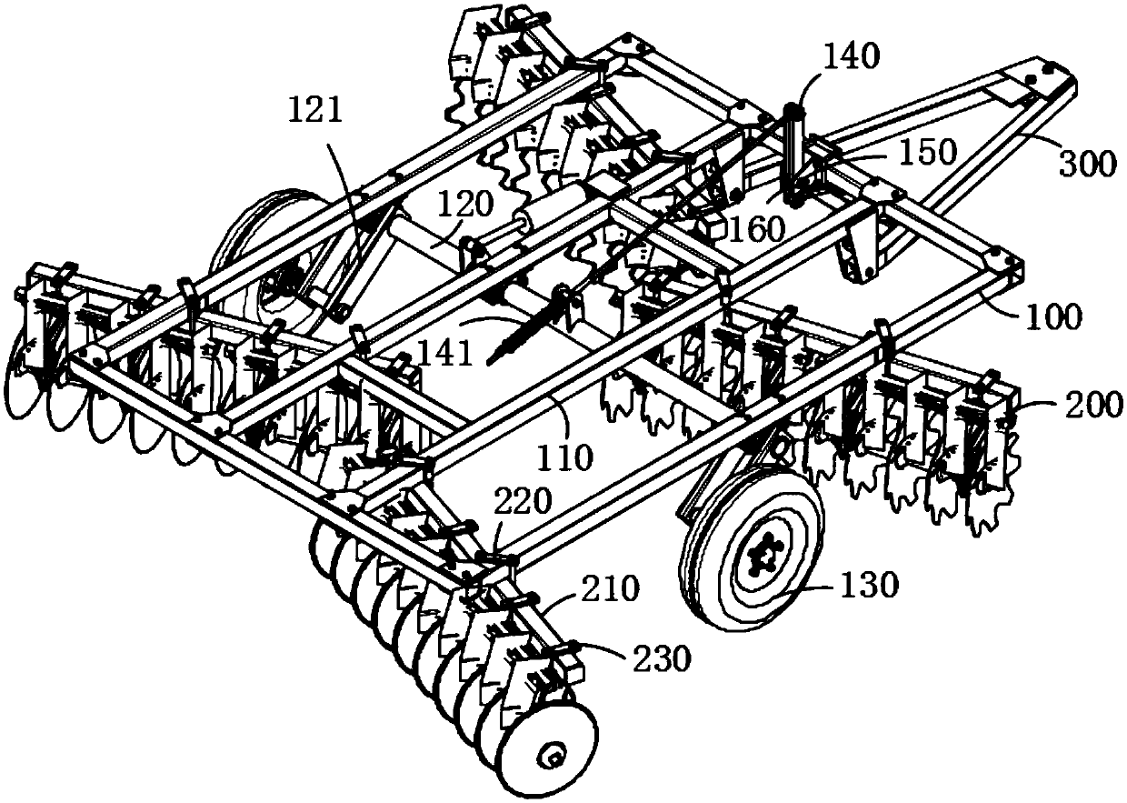
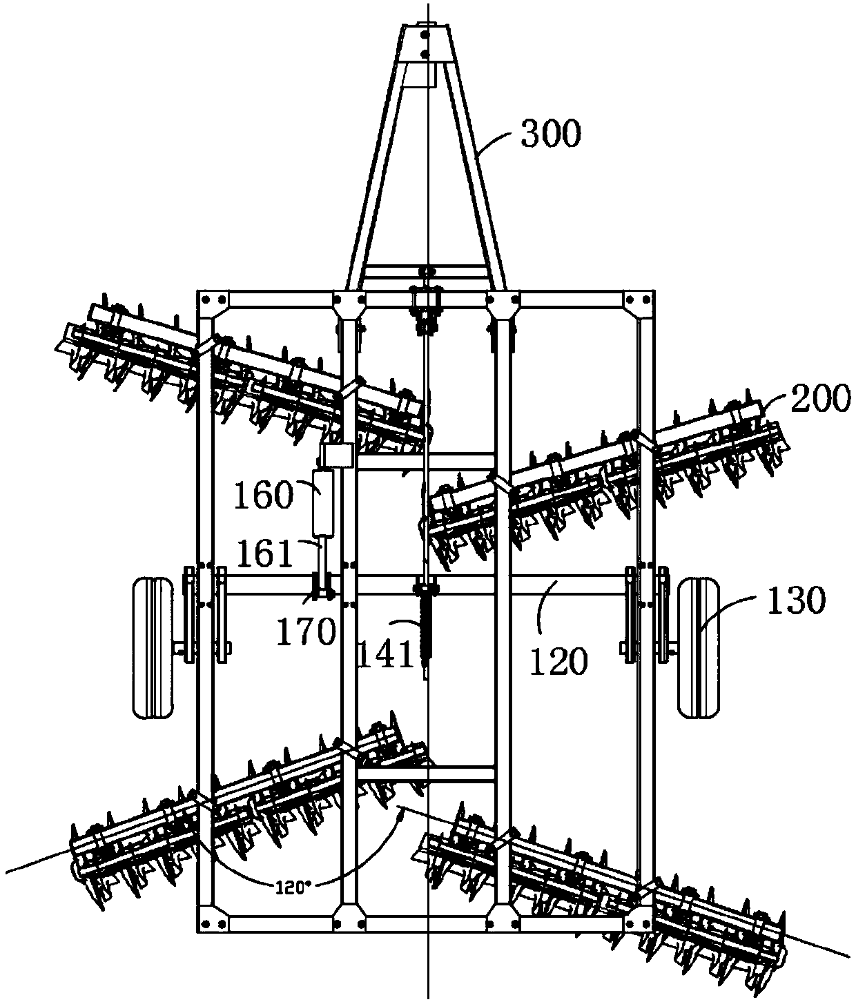
[0041] Refer to attached figure 1 , figure 2 and image 3 As shown, a new type of disc harrow in this embodiment includes a frame 100 and a plurality of rake groups 200, and a plurality of rake groups 200 are detachably connected to the frame 100, and the frame 100 is formed by welding a plurality of side beams 110 Square structure, the frame 100 is provided with a traction frame 300 along the direction of the axis of symmetry, the middle of the frame 100 is provided with a wheel shaft 120 transversely, the two ends of the wheel shaft 120 are provided with wheels 130, and the center of the frame 100 is provided with a link control mechanism 140, One end of the connecting rod control mechanism 140 is fixedly connected to the side beam 110 of the frame 100, and the other end is connected to the wheel shaft 120. A plurality of rake groups 200 are arranged alternately on both sides along the symmetrical axis of the frame 100. The adjacent two rake groups 200 The crossbeam 210 f...

Embodiment 2

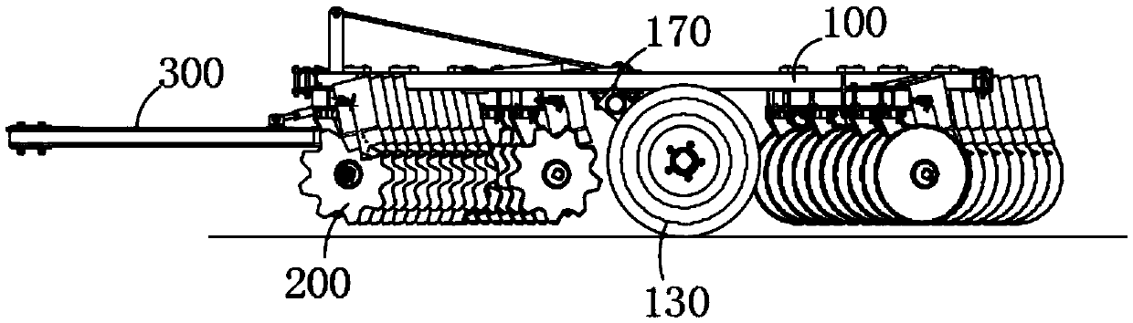
[0049] Refer to attached figure 1 , figure 2 , image 3 and Figure 4 As shown, the usage method of a new type of disc harrow in this embodiment is that the tractor drives the frame 100 forward, the cylinder 160 controls the wheel 130 to rise, and a plurality of harrow groups 200 work on the land.

[0050] The steps of the using method of the present embodiment are:

[0051] S100, move forward, the tractor drives the disc harrow to move forward to the target site;

[0052] S200, retracting the wheel, the cylinder 160 drives the connecting rod control mechanism 140 to slide and control the rotation of the wheel shaft 120 to lift the wheel 130 into the air and collect it;

[0053] S300, arable land, the tractor continues to drive the disc harrow forward, and the harrow group 200 plows and reclaims the land;

[0054] S400, put the wheel, after the work is finished, the cylinder 160 drives the connecting rod control mechanism 140 to return, and the wheel shaft 120 rotates to...


PUM


Abstract

The invention relates to a novel disc harrow and a using method thereof, and belongs to the technical field of disc harrows. The novel disc harrow comprises a rack and a plurality of harrow assemblies, wherein the harrow assemblies are detachably connected with the rack; the rack has a square structure formed by a plurality of side beams in a welded manner; the rack is provided with a traction rack in the symmetric axis direction; a wheel axle is transversely arranged in the middle of the rack; wheels are arranged at two ends of the wheel axle; a connecting rod control mechanism is arranged inthe middle of the rack; one end of the connecting rod control mechanism is fixedly connected with the side beams of the rack while the other end is connected with the wheel axle; the harrow assemblies are arranged on the two sides of the rack in a staggered manner along the symmetric axis of the rack; and the cross beams of each two adjacent harrow assemblies form an angle of 120 degrees; and thelowest end of each harrow assembly is lower than the lowest end of a wheel. The novel disc harrow has the advantages of high cultivation efficiency, large cultivation area, good effect, convenience in use and avoidance of loosening even if the harrow assemblies are used for a long time.

Description

technical field [0001] The invention belongs to the field of disc harrows, and more specifically relates to a new type of disc harrow and its usage method. Background technique [0002] The disc harrow is a traditional tillage tool in agricultural production, and it used to be one of the necessary farm tools for farmers. It is also one of the Chinese martial arts equipment, which evolved from farm tools. Iron-toothed rakes, with sharp teeth like nails, are highly aggressive and also function as weapons. Disc harrow is based on the principle of harrowing, with groups of concave discs as working parts. The plane of the cutting edge of the harrow is perpendicular to the ground and has an adjustable deflection angle with the direction of the unit. During operation, the rake rolls forward under the action of tractor traction and soil reaction force, the cutting edge of the rake cuts into the soil, cuts off the grass roots and crop residues, and makes the soil rise along the con...

Claims


Application Information

Patent Timeline
Patent Type & Authority Applications(China)
IPC IPC(8): A01B21/08A01B23/04A01B23/06
CPCA01B21/083A01B23/046A01B23/06
Inventor 刘汉武刘繁华王晓燕程俊争王福礁李兴凯
Owner 北京德邦大为科技股份有限公司
Why Eureka
Try Eureka