
Steel plate recycling bending machine capable of reducing scrap accumulation of auxiliary positioning jigs

A technology for auxiliary positioning and positioning fixtures, which is applied in the direction of cleaning methods and appliances, smoke and dust removal, chemical instruments and methods, etc., can solve the problems of iron filings accumulation and cleaning, and achieve good shock absorption effect

Active Publication Date: 2019-04-19
威海锦途精密金属有限公司
View PDF6 Cites 0 Cited by
  • Summary
  • Abstract
  • Description
  • Claims
  • Application Information

AI Technical Summary

Problems solved by technology

[0002] Steel plate recycling is also scrap iron recycling. Most of the used steel plates are rusted, broken or can no longer be supported and fixed. In order to ensure portability in recycling, some large-area steel plates need to be bent Processing, in the bending machine, in order to ensure the efficiency and accuracy of bending, there is often a positioning function. In this type of bent steel plate, the rusty iron filings on it will fall along with the bending, thus causing Falling iron filings accumulate in the corners of the positioning jig, making it difficult to clean

Method used


Image

  • Steel plate recycling bending machine capable of reducing scrap accumulation of auxiliary positioning jigs
  • Steel plate recycling bending machine capable of reducing scrap accumulation of auxiliary positioning jigs
  • Steel plate recycling bending machine capable of reducing scrap accumulation of auxiliary positioning jigs

Examples


Embodiment

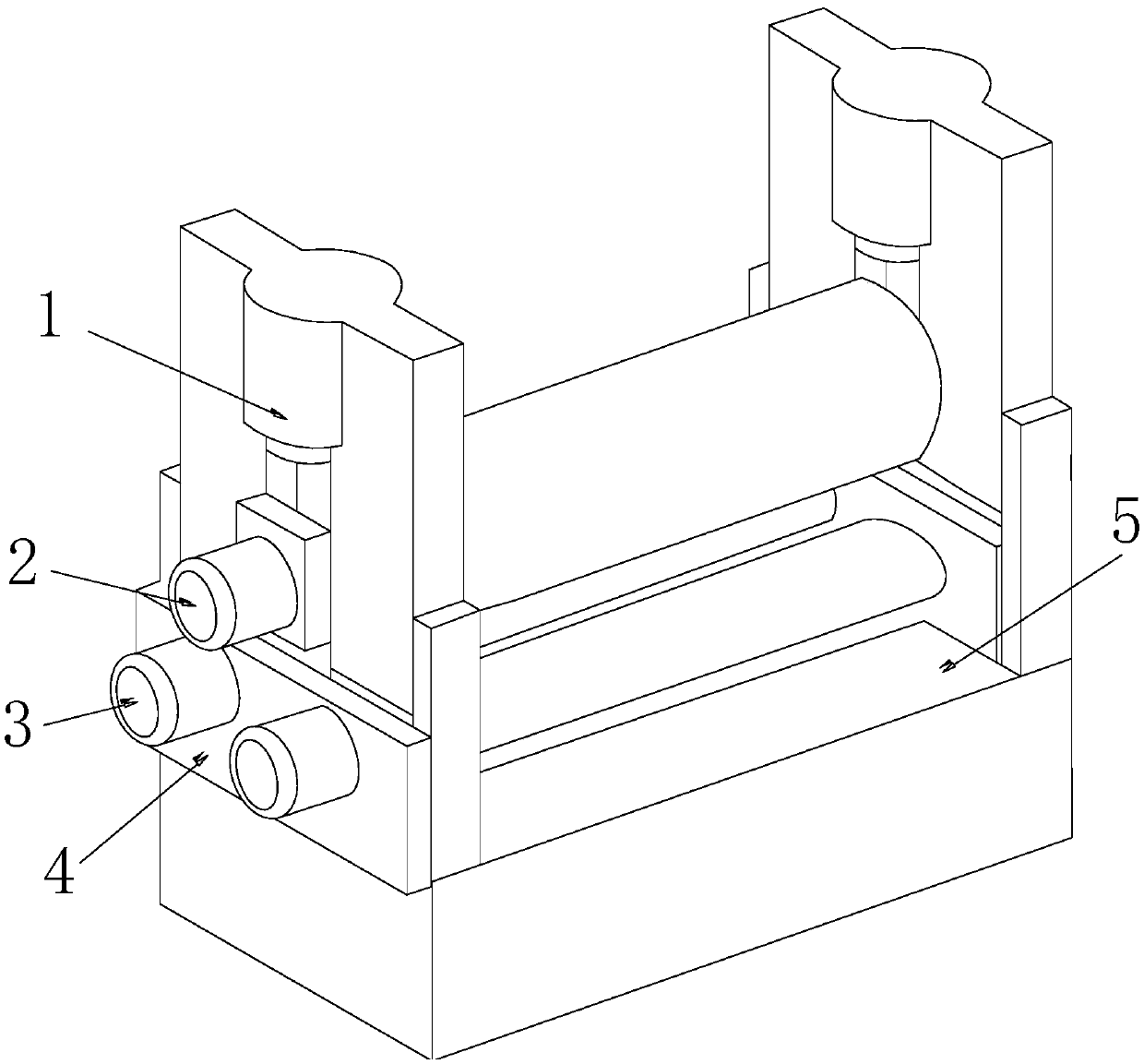
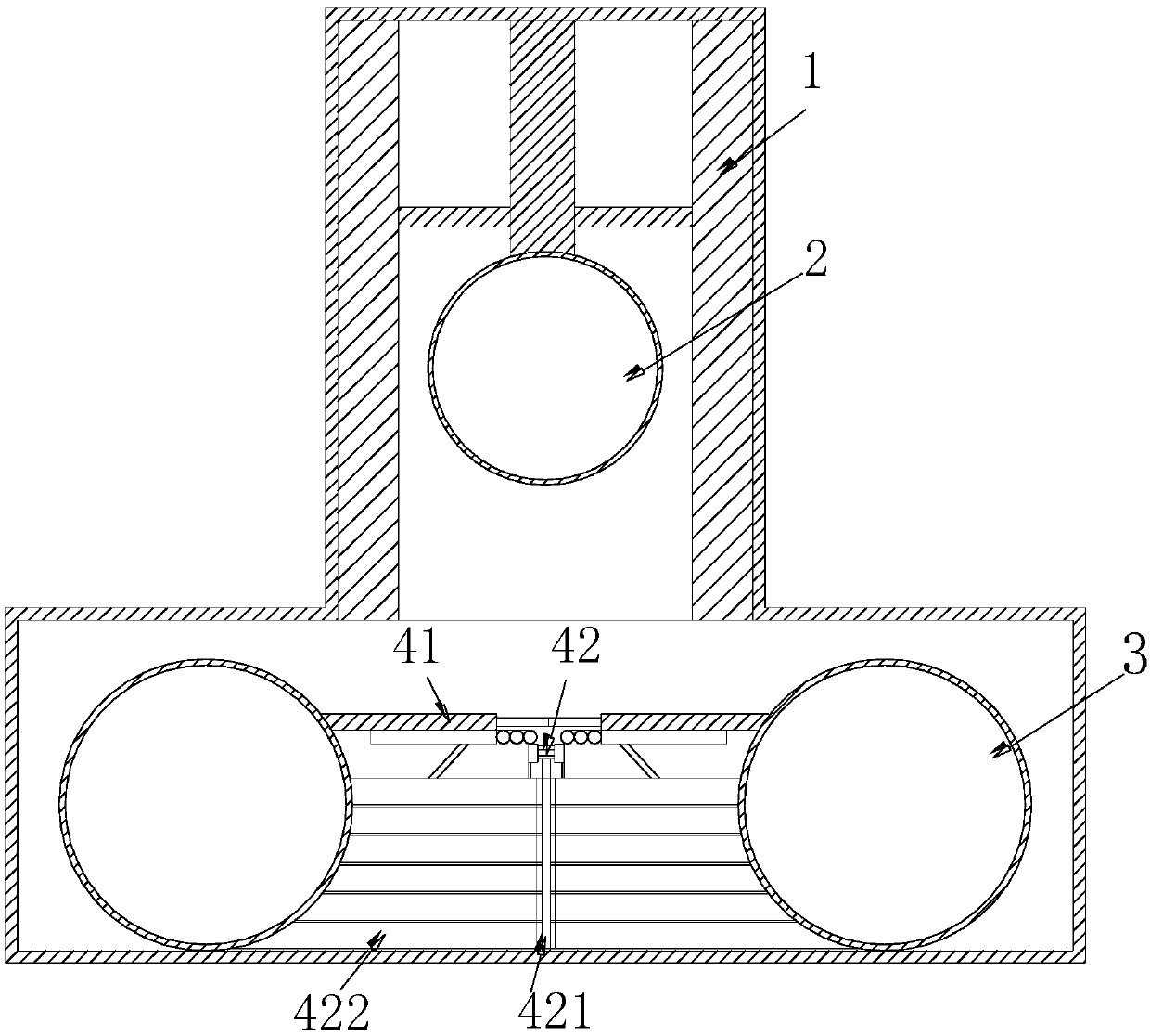
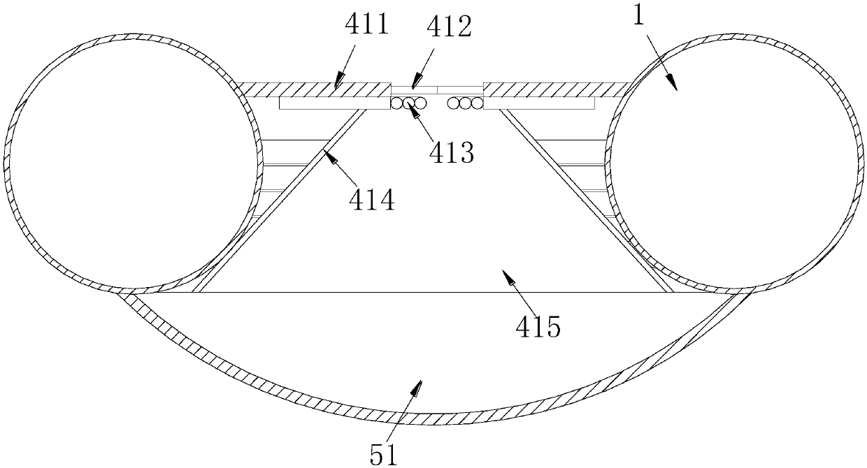
[0023] Such as Figure 1-Figure 4 As shown, the present invention provides a steel plate recovery bending machine that reduces the accumulation of auxiliary positioning jigs. Its structure includes a support plate 1, a clamping plate 2, a positioning roller 3, a positioning jig 4, and a workbench 5. A positioning jig 4 and a support plate 1 are installed on the table 5. The support plate 1 is installed vertically, and the positioning jig 4 is installed horizontally. The positioning jig 4 is equipped with two positioning rollers 3 that cooperate with each other. , The horizontal gap between the two positioning rollers 3 corresponds to the clamping plate 2, the clamping plate 2 is parallel to the positioning roller 3 up and down, and the clamping plate 2 is connected and fixed by the support plates 1 on both sides, A hinged opening and closing mechanism 41 and a negative pressure generator 42 are provided inside the positioning jig 4. The negative pressure generator 42 is provide...


PUM


Abstract

The invention discloses a steel plate recycling bending machine capable of reducing scrap accumulation of auxiliary positioning jigs. The steel plate recycling bending machine structurally comprises supporting plates, clamping plates, positioning rollers, the positioning jigs and a working table. The positioning jigs and the supporting plates are installed on the working table. The supporting plates are vertically installed. The positioning jigs are horizontally installed. The two positioning rollers matched with each other are arranged in the positioning jigs which are horizontally installed.The horizontal gap between the two positioning rollers corresponds to the clamping plates. The clamping plates and the positioning rollers are vertically parallel. The clamping plates are connected and fixed through the supporting plates on the two sides. According to the steel plate recycling bending machine, by means of cooperation of hinge joint opening and closing mechanisms and negative pressure generators, partition plates are driven to be automatically opened and closed through electric connection of movable rods and hinge joint telescopic rods; by controlling adsorption of negative pressure cavities through isolation and disconnection of the partition plates, accumulation of iron scrap left at corners during bending is reduced under negative pressure adsorption, and the beneficialeffects that the steel plate recycling bending machine is portable and clean are achieved.

Description

Technical field [0001] The invention relates to a steel plate recycling bending machine, in particular, a steel plate recycling bending machine which reduces the accumulation of debris on auxiliary positioning jigs. Background technique [0002] Steel plate recycling is also scrap iron recycling. Most of the used steel plates are rusty, broken, or can no longer be supported and fixed. To ensure portability during recycling, some large-area steel plates need to be bent In order to ensure the efficiency and accuracy of the bending, the bending machine is often equipped with a positioning function. In this type of bending steel plate, the rusty iron filings on the steel plate will fall along with the bending, thus causing The fallen iron filings accumulate in the corners of the positioning jig, causing difficulty in cleaning. Summary of the invention [0003] In view of the above-mentioned problems, the present invention provides a steel plate recovery bending machine that reduces t...

Claims


Application Information

Patent Timeline
IPC IPC(8): B08B7/02B08B15/04
CPCB08B7/02B08B15/04
Inventor 潘晓青
Owner 威海锦途精密金属有限公司
Learn More