A high-efficiency cleaning device for oil tanks

A cleaning device and high-efficiency technology, applied in the direction of cleaning hollow objects, cleaning methods and utensils, chemical instruments and methods, etc., can solve the problems of incomplete cleaning and small cleaning range, achieve good descaling effect, large cleaning range, and solve the problem of Small cleaning effect

Active Publication Date: 2021-08-06
CHINA PETROLEUM & CHEM CORP +1
View PDF0 Cites 0 Cited by
  • Summary
  • Abstract
  • Description
  • Claims
  • Application Information

AI Technical Summary

Problems solved by technology

[0004] The purpose of the present invention is to provide a high-efficiency oil tank cleaning device with large cleaning range and good cleaning effect to solve the problems of small cleaning range and incomplete cleaning in existing cleaning equipment

Method used


Image

  • A high-efficiency cleaning device for oil tanks
  • A high-efficiency cleaning device for oil tanks
  • A high-efficiency cleaning device for oil tanks

Examples


Embodiment Construction

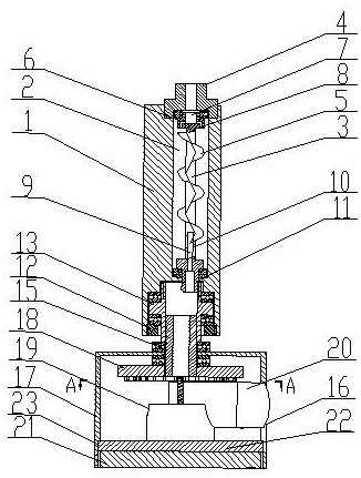
[0026] The high-efficiency oil tank cleaning device is composed of a main cylinder 1, a rotating chamber 2, a rotating shaft 3, and a rotating cleaning box. The main cylinder 1 is provided with a rotating chamber 2, and the top of the rotating chamber 2 is threaded with a joint 4. The joint 4 is in the shape of ⊥. The joint 4 communicates with the high-pressure water source through a connecting hose, and a central flow channel is arranged in the joint 4, so that the high-pressure water source enters the cleaning device through the joint 4, and the rotating shaft 3 is installed in the rotating chamber 2 below the joint 4 through ball bearings arranged up and down. .

[0027] The circumference of the rotating shaft 3 is spirally provided with blades 5, and the blades 5 are fixed on the rotating shaft 3. When the high-pressure water impacts on the blades 5, the blades 5 drive the rotating shaft 3 to rotate; the top of the rotating shaft 3 above the blades 5 is provided with a flan...


PUM


Abstract

The invention relates to a high-efficiency oil tank cleaning device, which belongs to the technical field of oil tank cleaning equipment. It is composed of a main cylinder, a rotating chamber, a rotating shaft and a rotating cleaning box. The main cylinder is provided with a rotating chamber, and the top of the rotating chamber is threaded with a joint ;In the rotating cavity below the joint, a rotating shaft is installed through a ball bearing, and an incomplete gear is fixedly installed at the lower end of the rotating shaft; in the rotating cavity below the incomplete gear, an assembly kit is movably installed through ball bearings and ring baffles arranged up and down. There is a rotating cleaning box below. The high-efficiency cleaning nozzle has a large cleaning range and good cleaning effect, which solves the problems of small cleaning range and incomplete cleaning in existing cleaning equipment, and meets the needs of industrial oil tank cleaning.

Description

technical field [0001] The invention relates to a high-efficiency cleaning device for an oil tank, which belongs to the technical field of oil tank cleaning equipment. Background technique [0002] Oil tanks are often used to store crude oil or oil products in the petrochemical field. After long-term use, a large amount of oil scale will appear on the inner wall of the oil tank, which will corrode the inner wall of the oil tank and seriously affect the service life of the oil tank. It will also induce oxidation and deterioration of oil products, which will cause harm to oil-using vehicles, so the oil tank needs to be cleaned regularly. [0003] Due to the volatility, flammability and explosiveness of oil products, manual cleaning has great potential safety hazards. However, the periodic rotation method adopted by the traditional cleaning nozzle has a narrow cleaning work zone, and the work belts cannot be completely overlapped, resulting in The area that can be cleaned duri...

Claims


Application Information

Patent Timeline
IPC IPC(8): B08B9/093
CPCB08B9/0936
Inventor 陈辉梁福元刘为民屈人伟文凤余勒卫东邱玲李旭夏成宇易先中
Owner CHINA PETROLEUM & CHEM CORP
Why Eureka
Try Eureka