Shock absorber assembly machine

A shock absorber and assembly machine technology, applied in assembly machines, metal processing, metal processing equipment and other directions, can solve the problems of difficult compression, large spring stiffness coefficient, and reduce the assembly efficiency of the shock absorber assembly, and achieve high compression efficiency. , the effect of increasing assembly efficiency

Inactive Publication Date: 2019-04-19
张超
View PDF0 Cites 1 Cited by
  • Summary
  • Abstract
  • Description
  • Claims
  • Application Information

AI Technical Summary

Problems solved by technology

[0002] In the production process of the shock absorber, the last process is to install the spring on the piston rod of the shock absorber, while the existing spring installation method is to manually put the spring on the piston rod of the shock absorber, Then the suspension ring is installed on the end of the spring to complete the installation of the spring, and in the prior art, in order to increase the damping strength of the shock absorber, it is necessary to require the spring to be in a compressed state after the assembly is completed, while the existing It is mainly assembled by hand. Therefore, in the process of assembling the shock absorber with a large specification, it is difficult to compress because of the large stiffness coefficient of the spring, which greatly increases the difficulty of assembling the shock absorber. Reduced assembly efficiency of the shock absorber assembly

Method used


Image

  • Shock absorber assembly machine
  • Shock absorber assembly machine

Examples


specific Embodiment approach

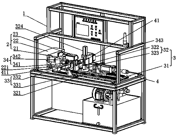
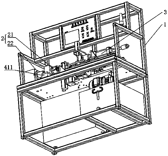
[0021]As an improved specific embodiment, the positioning mechanism 32 includes a positioning seat 321, a positioning cylinder 324, and a first positioning block 322 and a second positioning block 323 for the shock absorber to be placed. The first positioning block 322 and the second positioning block Both positioning blocks 323 are provided with slots for embedding shock absorbers, the first positioning block 322 is fixed on the positioning platform 31, and the positioning seat 321 is slidably arranged on the positioning platform 31. The second positioning block 323 is fixed on the positioning seat 321, the positioning cylinder 324 is arranged on the top of the second positioning block 323, and its push rod is set downwards, so as to be clamped with the slot of the second positioning block 323 by elongation. The shock absorber, through the cooperation of the first positioning block 322 and the second positioning block 323, can effectively use the embedded groove to realize the...

Embodiment approach

[0024] As an improved specific embodiment, the piston rod clamping mechanism 34 includes a fixed clamp block 341, a movable clamp block 342 and a clamping cylinder 343, and the fixed clamp block 341 is fixed on the spring stopper 332 facing away from the first position One side of the block 322, the clamping cylinder 343 is fixed on the position of the working platform 4 close to the spring baffle 332, and its push rod is set opposite to the fixed clamping block 341, and the movable clamping block 342 is fixed on the clamping cylinder 343 On the push rod of the clamping cylinder 343, the piston rod of the shock absorber is clamped by the clamping cylinder 343 and the fixed clamping block 341. Through the cooperation of the fixed clamping block 341 and the moving clamping block 342, the clamping cylinder 343 can be effectively used. Pushing action, the movable clamp block 342 and the fixed clamp block 341 are close to each other to clamp the piston rod, so that the piston rod ca...


PUM


Abstract

The invention discloses a shock absorber assembly machine. The machine comprises a frame, and a screwing device, a positioning extrusion device and a working platform arranged on the frame. The screwing device is arranged on the working platform; the positioning extrusion device is arranged on the working platform and is opposite to the screwing device; a shock absorber is fixedly located on the positioning extrusion device when assembled to make a spring compressed; a suspension ring is arranged in the screwing device, and is screwed into the end of a piston rod assembled to the shock absorber through the screwing device when the shock absorber spring is compressed. The shock absorber assembly machine can effectively locate the shock absorber and compress the spring by setting the positioning extrusion device; by setting the screwing device, the suspension ring is effectively screwed into the piston rod of the shock absorber after the shock absorber is positioned and the spring is compressed; thus, the shock absorber assembly machine can effectively achieve an automatic assembly effect and can greatly increase the shock absorber assembling efficiency.

Description

technical field [0001] The present invention relates to an assembly equipment, more specifically relates to a shock absorber assembly assembly machine. Background technique [0002] In the production process of the shock absorber, the last process is to install the spring on the piston rod of the shock absorber, while the existing spring installation method is to manually put the spring on the piston rod of the shock absorber, Then the suspension ring is installed on the end of the spring to complete the installation of the spring, and in the prior art, in order to increase the damping strength of the shock absorber, it is necessary to require the spring to be in a compressed state after the assembly is completed, while the existing It is mainly assembled by hand. Therefore, in the process of assembling the shock absorber with a large specification, it is difficult to compress because of the large stiffness coefficient of the spring, which greatly increases the difficulty of...

Claims


Application Information

Patent Timeline
Patent Type & Authority Applications(China)
IPC IPC(8): B23P21/00
CPCB23P21/002B23P19/006
Inventor 张超
Owner 张超
Why Eureka
Try Eureka