Spring and grid combined cushion seismic reduction device applicable to emergency rescue and disaster relief steel shed tunnels

A shock-absorbing device and spring buffering technology, which is applied in construction, protective equipment, etc., can solve the problems of large self-consumables and poor buffer energy consumption performance, and achieve rapid construction, improve the protection energy level of sheds and caves, and reduce impact effects force effect

Pending Publication Date: 2019-04-19
四川省交通勘察设计研究院有限公司
View PDF0 Cites 7 Cited by
  • Summary
  • Abstract
  • Description
  • Claims
  • Application Information

AI Technical Summary

Problems solved by technology

[0004] The technical problem to be solved by the present invention is: the top structure of the conventional shed has many self-heavy and consumable materials, and the buffer energy consumption performance is not good. Grille combined buffer and shock absorber

Method used


Image

  • Spring and grid combined cushion seismic reduction device applicable to emergency rescue and disaster relief steel shed tunnels
  • Spring and grid combined cushion seismic reduction device applicable to emergency rescue and disaster relief steel shed tunnels
  • Spring and grid combined cushion seismic reduction device applicable to emergency rescue and disaster relief steel shed tunnels

Examples


Embodiment 1

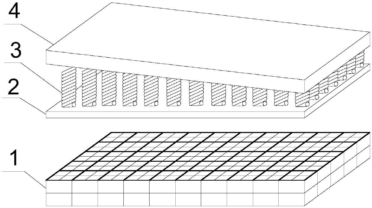
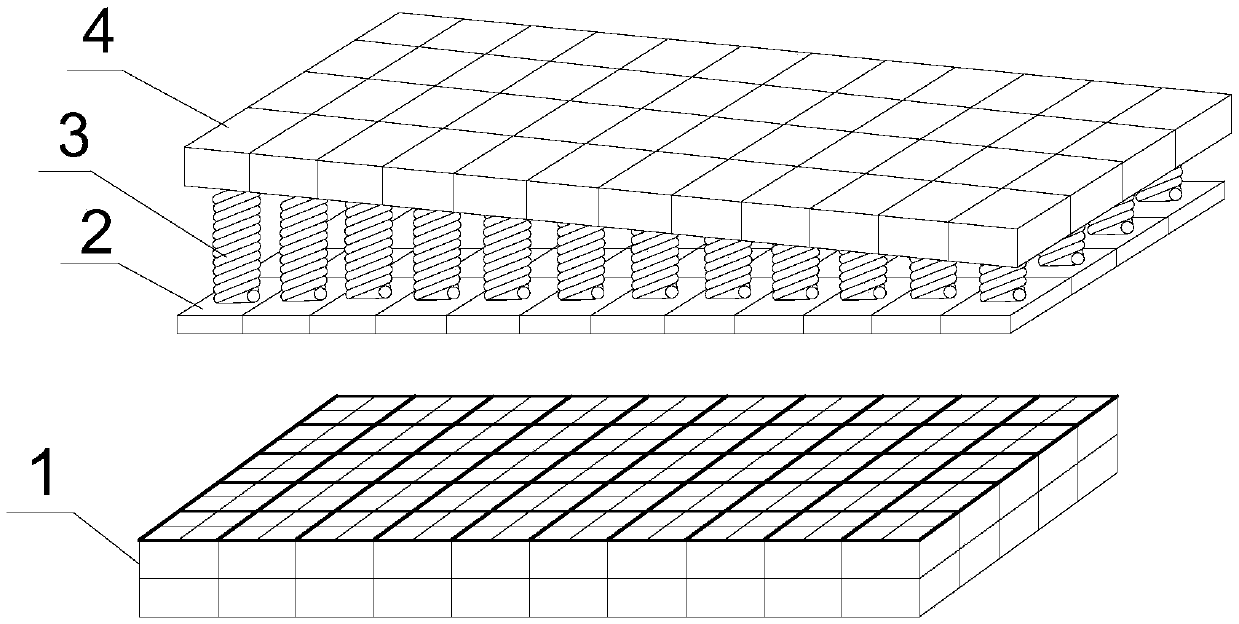
[0043] This embodiment provides a spring-grid combined buffering and shock-absorbing device suitable for emergency rescue and disaster relief steel shed holes, which is composed of two layers of a grid layer 1 and a spring buffer layer, and the grids are laid on the top of the steel shed hole frame from bottom to top in sequence Layer 1 and spring buffer layer; grid layer 1 includes N layers of grids stacked in sequence, N is a positive integer greater than or equal to 1, according to different protection levels, in this embodiment, 2 to 3 layers of grids are selected to be laid ; The spring buffer layer includes the first steel plate layer, several columnar springs 3 and the second steel plate layer from bottom to top.

Embodiment 2

[0045] Further improvement on the basis of Embodiment 1, each layer of grid is composed of multiple cuboid thin-walled boxes spliced ​​together, and each thin-walled box is divided into a plurality of square small grids by partitions; the thin-walled box The radial section has a rectangular structure, preferably a square structure. The axial bottom end of the thin-walled box is in contact with the top of the steel shed tunnel frame, and the axial top is in contact with the axial bottom end of the thin-walled box in the upper grid layer 1 or the first steel plate 2 contacts.

[0046] As a preferred solution, the thin-walled box can be made of aluminum, the dimensions of the thin-walled box are 1m×1m×0.5m, and the grid of the grid layer 1 is filled with polystyrene energy-absorbing buffer material.

Embodiment 3

[0048] Further improvement on the basis of Example 2, the first steel plate layer adopts a whole first steel plate 2, and the second steel plate layer adopts a whole second steel plate 4; the first steel plate 2 and the second steel plate 4 are arranged between A plurality of columnar springs 3 are evenly distributed, the bottom of the columnar springs 3 can be fixed on the upper surface of the first steel plate 2 with existing connecting plates and bolts, and the top of the columnar springs 3 can be fixed with existing connecting plates and bolts Be fixed on the lower surface on the second steel plate 4. A plurality of columnar springs 3 are arranged between the upper surface of the first steel plate 2 and the lower surface of the second steel plate 4 at a slope ratio of 1:5, and the second steel plate 4 is laid on the top of the columnar springs 3 at the same slope.


PUM


Abstract

The invention discloses a spring and grid combined cushion seismic reduction device applicable to emergency rescue and disaster relief steel shed tunnels. The spring and grid combined cushion seismicreduction device comprises a grid layer and a spring cushion layer. The grid layer and the spring cushion layer are sequentially laid on the top of a steel shed tunnel frame from bottom to top; the grid layer comprises N layers of grids, the grids are sequentially overlaid, and the N is a positive integer larger than or equal to 1; the spring cushion layer sequentially comprises a first steel plate layer, a plurality of columnar springs and a second steel plate layer from bottom to top. The spring and grid combined cushion seismic reduction device has the advantages that the spring and grid combined cushion seismic reduction device is a structural device with excellent steel shed tunnel cushion performance, construction speediness and high topographic condition adaptability, and is favorable for upgrading the protection levels of the shed tunnels, and the time can be gained for emergency rescue and disaster relief.

Description

technical field [0001] The invention relates to the field of road traffic safety protection facilities, in particular to a spring grid combined buffering and shock absorbing device suitable for emergency rescue and disaster relief steel shed holes. Background technique [0002] In recent years, after many geological disasters such as strong earthquakes and high-level landslides in mountainous areas, the rush to clear and maintain roads in mountainous areas with complex terrain conditions has become a "lifeline" project. How to quickly build special protective facilities in the event of geological disasters to provide a space for vehicle traffic safety is the focus of exploration by the transportation department and emergency rescue units. Practice has proved that the construction of temporary steel shed holes has become the preferred choice. [0003] However, high-level landslides have the characteristics of high energy and short impact time. Whether it is a temporary steel...

Claims


Application Information

Patent Timeline
Patent Type & Authority Applications(China)
IPC IPC(8): E01F7/04
CPCE01F7/045
Inventor 袁松黎良仆王希宝冉龙洲
Owner 四川省交通勘察设计研究院有限公司
Why Eureka
Try Eureka