Large flow nozzle-baffle structure

A baffle structure, large flow technology, applied in the direction of the lift valve, valve details, engine components, etc., can solve the problems of increasing the movement stroke of the solenoid valve actuator, increasing the opening, and the rapid solenoid valve cannot meet the use requirements, etc. Achieve the effect of simple structure, meeting the demand of large flow, and good sealing

Active Publication Date: 2019-04-19
XIAN AERO ENGINE CONTROLS
View PDF8 Cites 1 Cited by
  • Summary
  • Abstract
  • Description
  • Claims
  • Application Information

AI Technical Summary

Problems solved by technology

The flow rate of the solenoid valve is determined by the diameter of the oil hole in the center of the nozzle 1 and the opening of the baffle 2 and the nozzle 1. When a large flow output is required, the diameter of the oil hole in the center of the nozzle 1 needs to be increased while the baffle 2 is increased. The opening after the nozzle 1 is opened also means that the movement stroke of the solenoid valve ac

Method used


Image

  • Large flow nozzle-baffle structure
  • Large flow nozzle-baffle structure
  • Large flow nozzle-baffle structure

Examples


Embodiment Construction

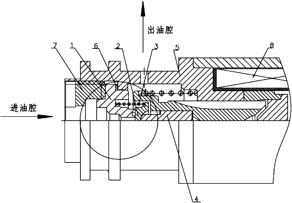
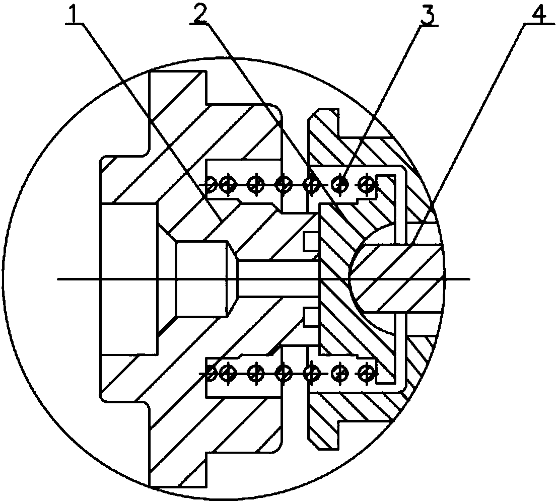
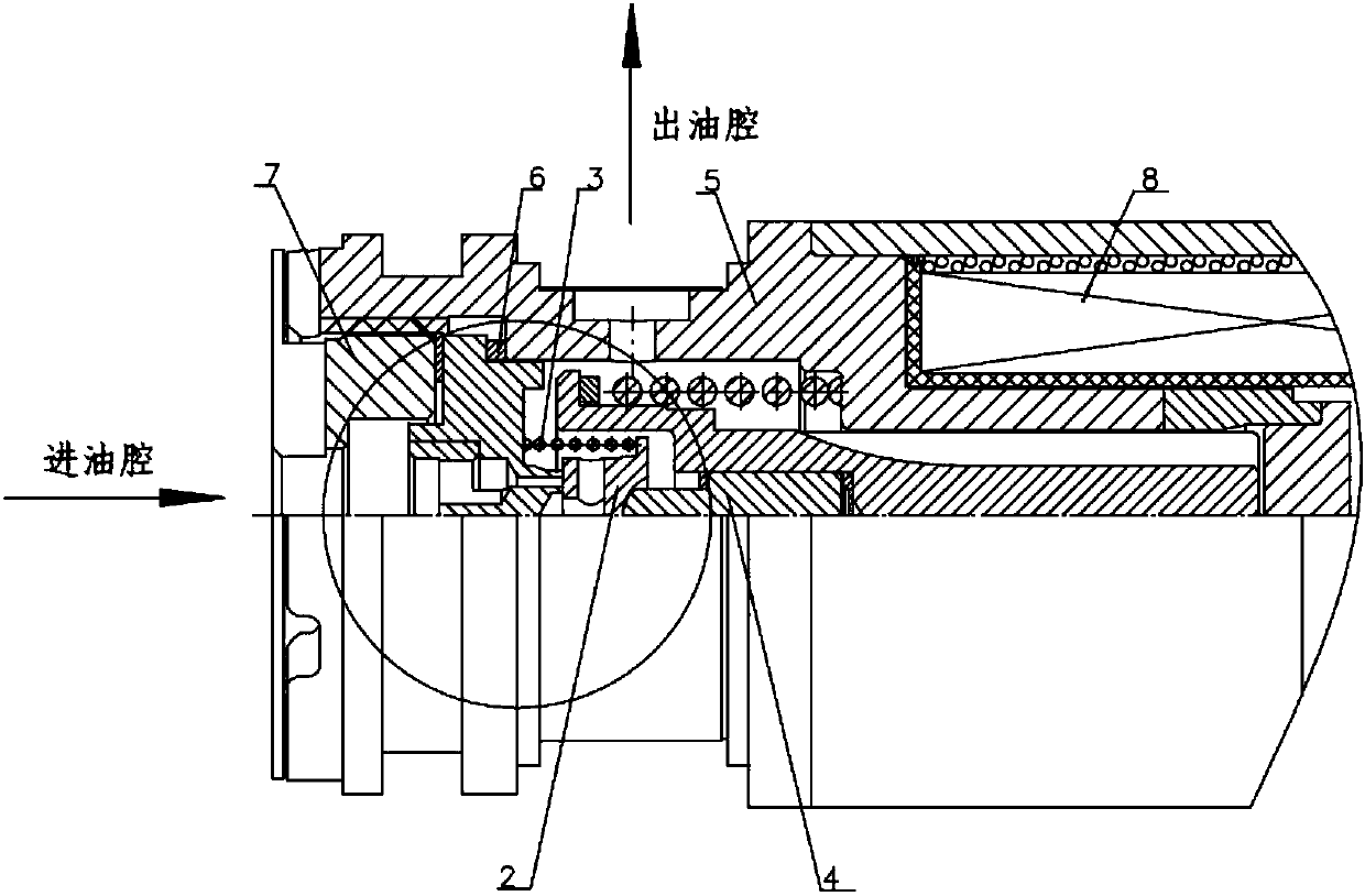
[0015] A large flow nozzle-baffle plate structure, its functional structure includes: the nozzle assembly is composed of a porous nozzle 9 and a nozzle seat 10, a baffle plate 2, a spring 3, a solenoid valve actuator 4, a housing 5, a sealing gasket 6, a screw Plug 7, electromagnet unit 8;

[0016] The porous oil nozzle 9 has a stepped shaft shape, and the outside is divided into two sections, and the outer diameter decreases successively from left to right. The left end of the porous oil nozzle 9 has a central blind hole 9a, and the bottom surface of the blind hole is opened with uniformly distributed oil holes 9b and The junction surfaces of the two outer cylindrical sections are connected, and the right end surface of the porous nozzle 9 has a central blind hole 9c that forms a uniform sealing ring with the outer cylindrical surface; the nozzle seat 10 has a stepped shaft shape, and the inner central through hole is divided into 3 sections, from left to right They are respe...


PUM


Abstract

The invention relates to a multihole nozzle-baffle structure, in particular to a multihole nozzle-baffle structure of a large-flow rapid electromagnetic valve, belonging to the technical field of electro-hydraulic conversion devices. The multihole nozzle-baffle structure comprises a nozzle assembly, a baffle (2) and a shell (5), wherein the nozzle assembly and the baffle (2) are sealed by an end face and are arranged in the shell (5); an oil hole communicating the outside world with a cavity in which the baffle is located is formed in the shell (5); and an oil outlet of the nozzle assembly isan annular oil passage. The large flow nozzle-baffle structure provided by the invention achieves the effect of large flow output under the stroke of a relatively small electromagnet core, enables anelectromagnet unit to be easily driven, has good sealing performance and simple structure, is safe and reliable and satisfies the requirement of an existing fuel regulator on large flow.

Description

technical field [0001] The invention relates to a porous nozzle-baffle plate structure, in particular to a porous nozzle-baffle plate structure of a high-flow fast electromagnetic valve, and belongs to the technical field of electro-hydraulic conversion devices. Background technique [0002] The existing fast solenoid valve adopts the traditional nozzle-baffle structure to realize the closing and opening of the solenoid valve, refer to figure 1 , mainly includes: nozzle 1, baffle plate 2, spring 3, solenoid valve actuating mechanism 4, housing 5, sealing washer 6, screw plug 7, electromagnet unit 8. The nozzle 1 is provided with a central oil hole, one end of the baffle 2 is a plane, and the other end is provided with a ball socket which conflicts with the solenoid valve actuating mechanism 4; Under the action of 4, it rests against the right end face of the nozzle 1 to form an end face seal, the inlet and outlet are shut off by the baffle 2, and the fast solenoid valve is ...

Claims


Application Information

Patent Timeline
IPC IPC(8): F16K31/06F16K1/32
CPCF16K1/32F16K31/0655F16K31/0675
Inventor 尉晓英吕梅明刘晨徵江君刘格王瑞
Owner XIAN AERO ENGINE CONTROLS
Why Eureka
Try Eureka