
Power cable partial discharge positioning system based on solenoid high-voltage wire and detection method

A cable partial discharge and positioning system technology, applied in the direction of measuring electricity, measuring devices, measuring electrical variables, etc., can solve the problems of ineffective identification and positioning

Pending Publication Date: 2019-04-19
STATE GRID JIANGSU ELECTRIC POWER CO ELECTRIC POWER RES INST +3
View PDF7 Cites 2 Cited by
  • Summary
  • Abstract
  • Description
  • Claims
  • Application Information

AI Technical Summary

Problems solved by technology

The actual field application shows that the damped oscillatory wave equipment applied to the distribution network power cable test can effectively detect and locate the partial discharge of the tested distribution network power cable body and the intermediate joint; The oscillatory wave equipment adopts the traveling wave positioning method for partial discharge positioning, and the traveling wave waveforms of the cable test end terminal and the remote terminal are consistent, so the existing single-ended sampling damped oscillatory wave equipment is very accurate for the partial discharge at the power cable terminal of the distribution network. There is a positioning blind area, and the partial discharge can only be detected at the terminal, but it cannot be effectively distinguished and located whether the partial discharge is located at the near-end (test end) terminal or the far-end terminal

Method used


Image

  • Power cable partial discharge positioning system based on solenoid high-voltage wire and detection method
  • Power cable partial discharge positioning system based on solenoid high-voltage wire and detection method
  • Power cable partial discharge positioning system based on solenoid high-voltage wire and detection method

Examples


Embodiment Construction

[0020] The technical solution of the present invention will be further described below in conjunction with the drawings and embodiments.

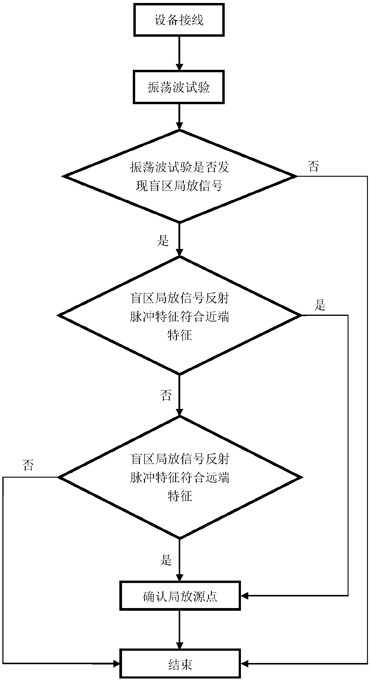
[0021] Such as figure 1 Shown is a schematic diagram of the connection of the present invention used in the actual site. The power cable partial discharge positioning system based on solenoid high-voltage lines of the present invention includes damping oscillating wave equipment and solenoid high-voltage lines. The damped oscillating wave equipment includes a high-voltage power supply module, a circuit module that generates damped oscillating waves, and a data processing module for partial discharge analysis. The data processing module contains partial discharge pulse analysis software, which has a waveform expansion analysis function. The damped oscillatory wave equipment also includes a standard pulse calibrator. The output end of the high-voltage source of the damped oscillatory wave device is connected to the spiral tube high-voltage line,...


PUM


Abstract

The invention discloses a power cable partial discharge positioning system based on a solenoid high-voltage wire and a detection method thereof. The system comprises a damping oscillation wave deviceand the solenoid high-voltage wire, wherein a high-voltage source output end of the damping oscillation wave device is connected with the solenoid high-voltage wire, and the other end of the solenoidhigh-voltage wire is connected with the near end of a to-be-tested cable, wherein quick connectors are adopted during connection. A blind area positioning detection process comprises the following steps of when an oscillation wave test of a distribution network cable is carried out, inserting a section of solenoid high-voltage wire without local discharge between an oscillation wave host machine and the to-be-detected cable as an auxiliary positioning device, identifying a direct pulse and a reflected pulse, and judging discharge positions according to the waveform characteristics. The deviceand the method can be matched with different types of distribution network cable damping oscillation wave equipment of different manufacturers under the condition that accessories and field workload are increased at the minimum limit, and partial discharge sources positioned at a near-end terminal and a far-end terminal can be quickly and accurately distinguished.

Description

Technical field [0001] The invention relates to a detection system for power cable oscillation wave test and a method for testing partial discharge, in particular to a power cable terminal partial discharge positioning system and detection method based on a spiral tube high-voltage line. Background technique [0002] Damped oscillating wave detection technology is a new technology used for power cable field condition detection and diagnosis that has been paid close attention in recent years at home and abroad. It has good equivalence with power frequency voltage, short action time, non-destructive testing, and easy to carry. Advantages. With the development of power systems and the increasing requirements of users for power supply reliability, damped oscillatory wave technology has been widely used in the field of state detection of power cables, especially power cables in distribution networks. There are corresponding power industry standards for the application of damped oscill...

Claims


Application Information

Patent Timeline
Patent Type & Authority Applications(China)
IPC IPC(8): G01R31/12
CPCG01R31/1272
Inventor 李陈莹陈杰胡丽斌曹京荥谭笑刘洋郑柒拾丁鹏刘彦马俊方
Owner STATE GRID JIANGSU ELECTRIC POWER CO ELECTRIC POWER RES INST
Learn More