Twisted wire pin automatic cutting and welding device

A technology of automatic cutting and welding devices, which is applied in the direction of connection, contact manufacturing, circuit/collector parts, etc., and can solve the problems of low output and yield

Active Publication Date: 2019-04-19
武汉华中激光产业有限公司
View PDF5 Cites 7 Cited by
  • Summary
  • Abstract
  • Description
  • Claims
  • Application Information

AI Technical Summary

Problems solved by technology

[0003] The purpose of the present invention is to provide an automatic cutting and welding device for stranded wire insertion pins, which is used to solve the problem of low output and yield in the traditional technology because the cutting process and welding process are manually completed on two equipments respectively

Method used


Image

  • Twisted wire pin automatic cutting and welding device
  • Twisted wire pin automatic cutting and welding device
  • Twisted wire pin automatic cutting and welding device

Examples


Embodiment 1

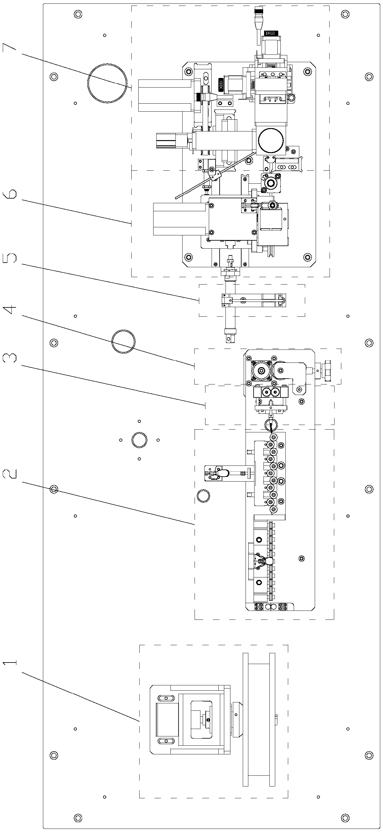
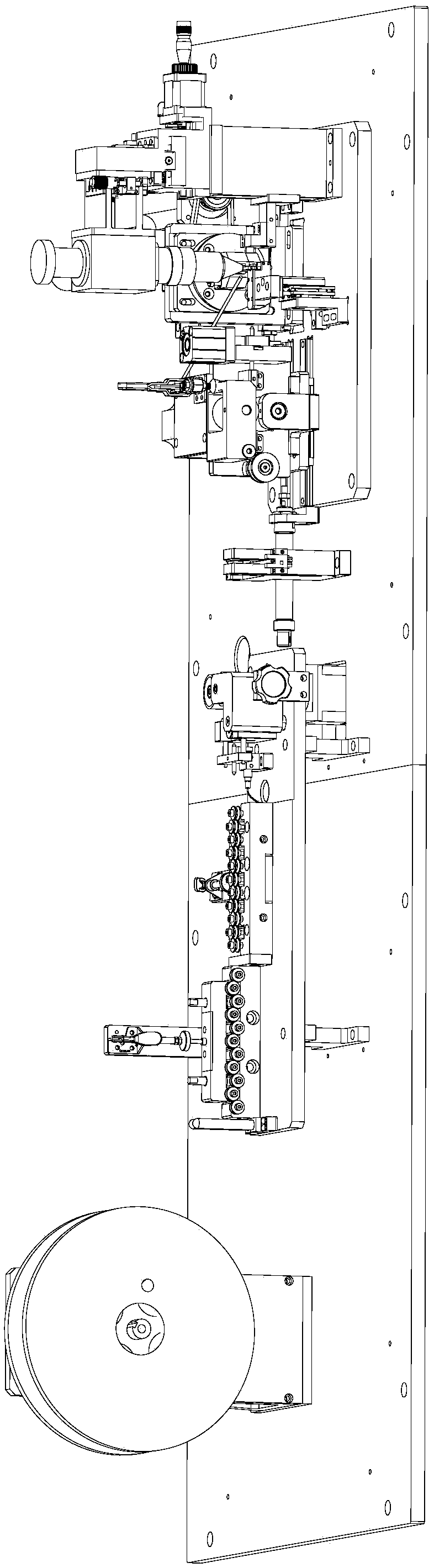
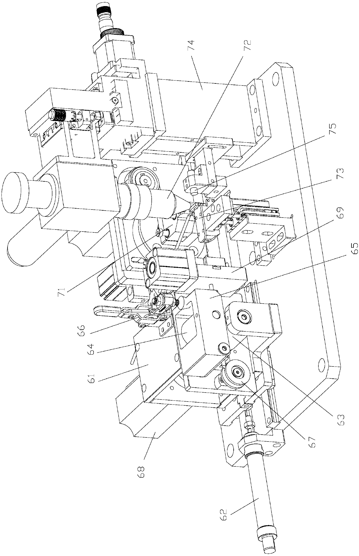
[0036] An automatic cutting and welding device for stranded wire pins, including a cutting and welding mechanism, the cutting and welding mechanism includes a cutting mechanism 6 and a welding mechanism 7; the cutting mechanism 6 includes a translation slide 61 driven by a driving cylinder 62, and the translation A shearing module 69 and a wire feeding mechanism for feeding the wires to the shearing module 69 are installed on the slide table 61. The wire feeding mechanism includes an active wire feeding wheel 63 and a driven wire feeding wheel 64 that cooperate with each other. The wheel 63 is driven by the wire feeding motor 68; the welding mechanism 7 includes a rotary fixture 71, a laser welding head 72 and a lifting platform 73, and the table top of the lifting platform 73 is connected to the outlet of the shearing module 69 and the clip of the rotary fixture 71 The laser welding head 72 faces the jaws of the rotary fixture 71 (the rotary fixture 71 includes a clamping moto...

Embodiment 2

[0043] On the basis of Embodiment 1, this embodiment also includes a pay-off mechanism 1, which includes a wire reel support 11 and a tension adjuster 13 installed on the reel support 11, on which the tension adjuster 13 Feeding wire reel 12 is installed.

[0044] The wire-releasing mechanism 1 is located at the front end of the whole device and is used for wire-releasing. The tension regulator 13 is used to control the pay-off speed of the pay-off reel 12 .

Embodiment 3

[0046] On the basis of embodiment two (or one), this embodiment also includes a backguy straightening mechanism 2 positioned in front of the cutting mechanism 6, and the backguy straightening mechanism 2 includes two straightening mechanisms and a backguy mechanism 4, two Two straightening mechanisms and a wire pulling mechanism 4 are arranged on a support plate 21 in a straight line along the trend of the twisted wire, wherein one straightening mechanism is arranged horizontally, and the other straightening mechanism is vertically arranged; said straightening mechanism includes a comb Shape straightening wheel installs fixed part 23 and a comb-shaped straightening wheel installs movable part 24, and each comb tooth of described comb-shaped straightening wheel installs fixed part 23 and comb-shaped straightening wheel installs movable part 24 The ends are all provided with straightening wheels 25, and the straightening wheel installation fixture 23 is fixedly installed on the s...


PUM


Abstract

The invention belongs to the technical field of a twisted wire pin production devices and particularly relates to a twisted wire pin automatic cutting and welding device comprising a cutting and welding mechanism. The cutting and welding mechanism comprises a cutting mechanism and a welding mechanism. The cutting mechanism comprises a shearing module and a wire feeding mechanism for feeding a wireto the shearing module. The welding mechanism comprises a rotating clamp, a laser welding head and a lifting platform. The tabletop of the lifting platform is connected to the discharging port of theshearing module and the clamping jaw of the rotating clamp. The laser welding head rightly faces the clamping jaw of the rotating clamp.

Description

technical field [0001] The invention belongs to the technical field of stranded wire pin production equipment, and in particular relates to an automatic cutting and welding device for stranded wire pins. Background technique [0002] Twisted elastic pins (commonly known as twist pins) are reverse twisted by two layers of multi-strand copper wires, and the two ends are welded into bundles. Small size, reliable contact characteristics, widely used in electronic components. Generally, the twisted 0.2-0.7 mm diameter beryllium copper stranded wire is automatically finely straightened, cut to length, and the two ends are automatically welded by laser welding. Before this, the manual straightening process was used. First, the stranded wires were straightened, and then cut into individual strands manually, and then manually loaded into the carrier one by one, and then put the carrier into the welding station. , laser welding one by one, the various links in the process are cumber...

Claims


Application Information

Patent Timeline
Patent Type & Authority Applications(China)
IPC IPC(8): H01R43/16H01R43/02
CPCH01R43/0221H01R43/16
Inventor 高峰
Owner 武汉华中激光产业有限公司
Why Eureka
Try Eureka