Stranded wire pin automatic cutting welding device
A technology of automatic cutting and welding devices, which is applied in the direction of connection, contact manufacturing, circuit/collector parts, etc., and can solve the problems of low output and yield
- Summary
- Abstract
- Description
- Claims
- Application Information
AI Technical Summary
Problems solved by technology
Method used
Image
Examples
Embodiment 1
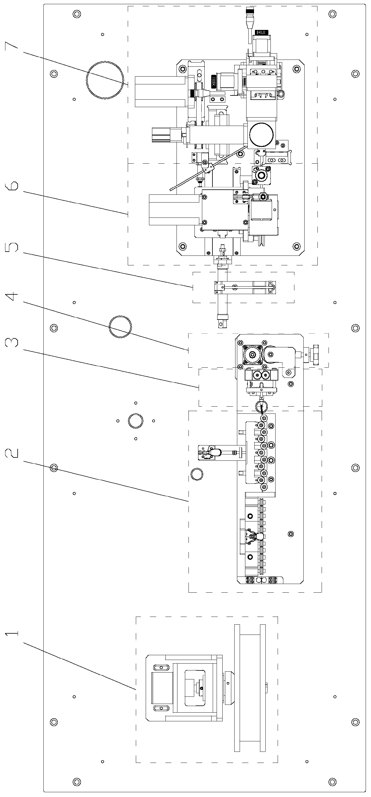
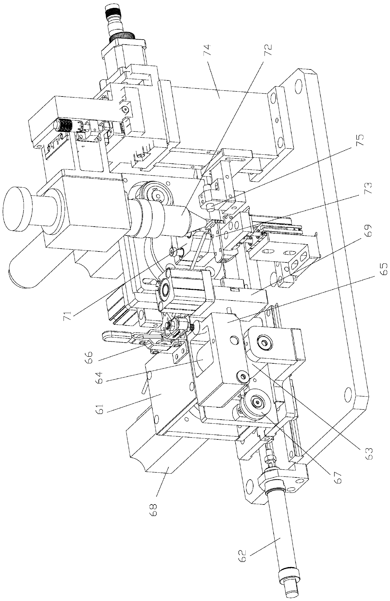
[0036] An automatic cutting and welding device for stranded wire pins, including a cutting and welding mechanism, the cutting and welding mechanism includes a cutting mechanism 6 and a welding mechanism 7; the cutting mechanism 6 includes a translation slide 61 driven by a driving cylinder 62, and the translation A shearing module 69 and a wire feeding mechanism for feeding the wires to the shearing module 69 are installed on the slide table 61. The wire feeding mechanism includes an active wire feeding wheel 63 and a driven wire feeding wheel 64 that cooperate with each other. The wheel 63 is driven by the wire feeding motor 68; the welding mechanism 7 includes a rotary fixture 71, a laser welding head 72 and a lifting platform 73, and the table top of the lifting platform 73 is connected to the outlet of the shearing module 69 and the clip of the rotary fixture 71 The laser welding head 72 faces the jaws of the rotary fixture 71 (the rotary fixture 71 includes a clamping moto...
Embodiment 2
[0043] On the basis of Embodiment 1, this embodiment also includes a pay-off mechanism 1, which includes a wire reel support 11 and a tension adjuster 13 installed on the reel support 11, on which the tension adjuster 13 Feeding wire reel 12 is installed.
[0044] The wire-releasing mechanism 1 is located at the front end of the whole device and is used for wire-releasing. The tension regulator 13 is used to control the pay-off speed of the pay-off reel 12 .
Embodiment 3
[0046] On the basis of embodiment two (or one), this embodiment also includes a backguy straightening mechanism 2 positioned in front of the cutting mechanism 6, and the backguy straightening mechanism 2 includes two straightening mechanisms and a backguy mechanism 4, two Two straightening mechanisms and a wire pulling mechanism 4 are arranged on a support plate 21 in a straight line along the trend of the twisted wire, wherein one straightening mechanism is arranged horizontally, and the other straightening mechanism is vertically arranged; said straightening mechanism includes a comb Shape straightening wheel installs fixed part 23 and a comb-shaped straightening wheel installs movable part 24, and each comb tooth of described comb-shaped straightening wheel installs fixed part 23 and comb-shaped straightening wheel installs movable part 24 The ends are all provided with straightening wheels 25, and the straightening wheel installation fixture 23 is fixedly installed on the s...
PUM
 Abstract
Description
Claims
Application Information
 - R&D
- Intellectual Property
- Life Sciences
- Materials
- Tech Scout
- Unparalleled Data Quality
- Higher Quality Content
- 60% Fewer Hallucinations
Browse by: Latest US Patents, China's latest patents, Technical Efficacy Thesaurus, Application Domain, Technology Topic, Popular Technical Reports.
© 2025 PatSnap. All rights reserved.Legal|Privacy policy|Modern Slavery Act Transparency Statement|Sitemap|About US| Contact US: help@patsnap.com


