Resonant converter

A resonant converter and resonant conversion technology, applied in high-efficiency power electronic conversion, output power conversion device, AC power input conversion to DC power output, etc., can solve the problem of affecting phase calculation or phase control dynamic performance, phase-locked loop phase Synchronization difficulties and errors, increased line costs and other issues, to achieve the effect of improving light load efficiency, simplifying circuit design and control, and reducing line costs

Active Publication Date: 2019-04-19
CHICONY POWER TECH CO LTD
View PDF5 Cites 4 Cited by
  • Summary
  • Abstract
  • Description
  • Claims
  • Application Information

AI Technical Summary

Problems solved by technology

[0005] The purpose of the present invention is to provide a resonant converter, which solves the problems of increased line cost and complex control caused by the additional use of a phase-locked loop, and the difficulty and error of phase synchronization in the phase-locked loop during light-load operation, which greatly reduces the Problems affecting the dynamic performance of phase calculations or phase control

Method used


Image

  • Resonant converter
  • Resonant converter
  • Resonant converter

Examples


Embodiment Construction

[0071] Hereby, the technical content and detailed description of the present invention are described as follows in conjunction with the drawings.

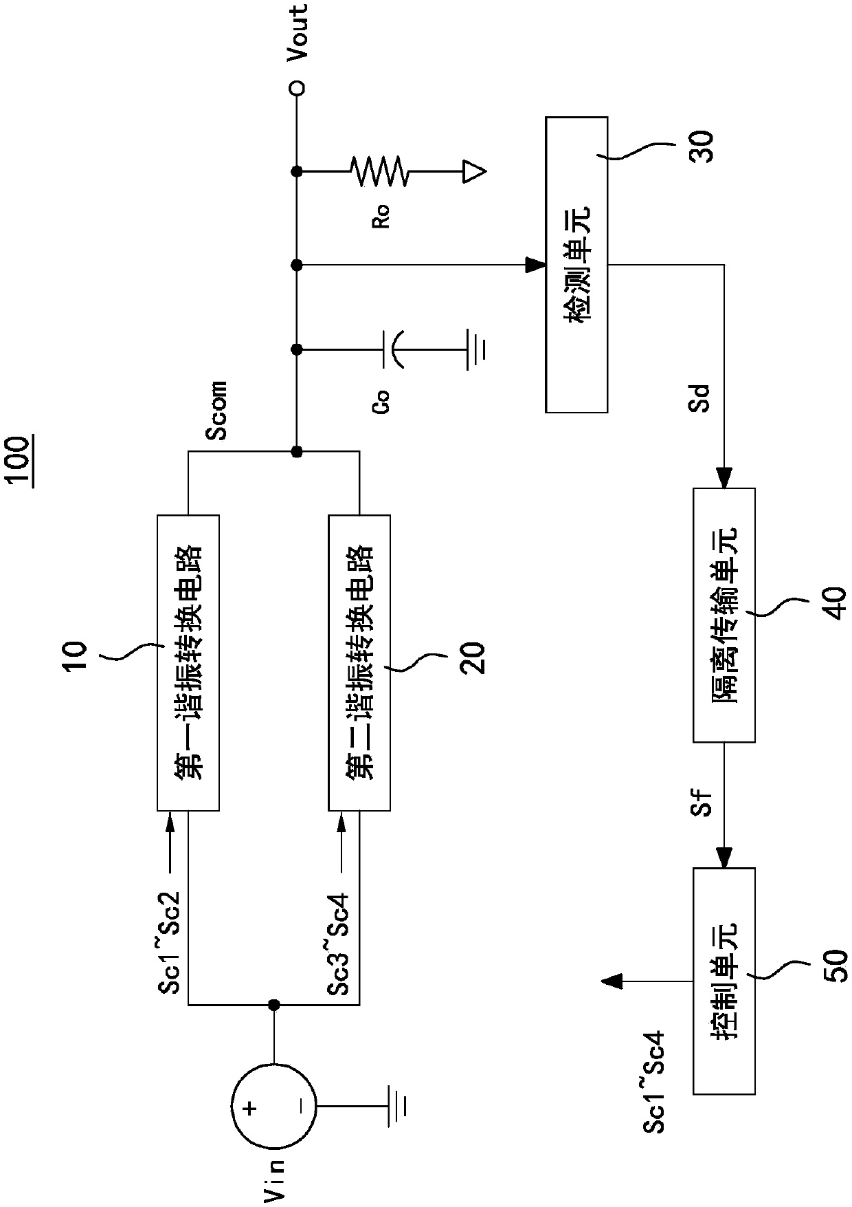
[0072] See figure 1 As shown, it is a block diagram of the first embodiment of the resonant converter of the present invention. The resonant converter 100 includes a first resonant conversion circuit 10 , a second resonant conversion circuit 20 , a detection unit 30 , an isolation transmission unit 40 and a control unit 50 .

[0073] The first resonant conversion circuit 10 is coupled to the second resonant conversion circuit 20 in parallel, and output sides of the first resonant conversion circuit 10 and the second resonant conversion circuit 20 are coupled to each other to form a common output side Scom. The first resonant conversion circuit 10 and the second resonant conversion circuit 20 receive an input power Vin and convert the input power Vin to an output power Vout. In this embodiment, the input power Vin and the output p...


PUM


Abstract

The present invention provides a resonant converter. The resonant converter includes a first resonant conversion circuit, a second resonant conversion circuit, and a control unit. The first resonant conversion circuit has a first switch element and a second switch element, and the first switch element is ungrounded coupled to the second switch element and the second switch element is grounded. Thesecond resonant conversion circuit has a third switch element and a fourth switch element, and the third switch element is ungrounded coupled to the fourth switch element and the fourth switch element is grounded. The control unit receives a feedback signal and controls the first resonant conversion circuit and the second resonant conversion circuit according to the feedback signal. Accordingly,it is to simplify circuit controls and increase the dynamic performance of phase controls.

Description

technical field [0001] The invention relates to a power converter, especially a resonant converter. Background technique [0002] Generally, the secondary side of a common resonant circuit mostly uses a full-wave rectifier composed of a center-tapped transformer and two diodes. The two diodes on the secondary side of this structure will convert the high-frequency sine wave from the primary side of the transformer to the secondary side. Cheng is a positive half-wave. Because of the characteristics of this full-wave rectification, two sets of converters with different phases must be used to drive in parallel, and the control signals need to be interleaved at 90 degrees to achieve the effect of phase cancellation and reduce the output ripple of the resonant circuit. [0003] A common method is to add an additional phase-locked loop (PLL) to the control circuit, and use this type of phase control circuit to make the output of two parallel converters accurately achieve 90-degree...

Claims


Application Information

Patent Timeline
Patent Type & Authority Applications(China)
IPC IPC(8): H02M7/48
CPCH02M7/48H02M7/4815H02M3/01H02M3/33571H02M3/285H02M3/3376Y02B70/10Y02P80/10H02M1/0032H02M1/0058
Inventor 邱焕智
Owner CHICONY POWER TECH CO LTD
Why Eureka
Try Eureka