
Devic and method for detecting fluorescent and phosphorescent light

A kind of equipment and phosphorescence technology, which is applied in the direction of fluorescence/phosphorescence, banknote authenticity inspection, instruments, etc., and can solve the problems of low excitation rate of phosphorescence identification marks, complex structure of the device, and low intensity

Inactive Publication Date: 2002-12-18
GIESECKE & DEVRIENT GMBH
View PDF4 Cites 2 Cited by
  • Summary
  • Abstract
  • Description
  • Claims
  • Application Information

AI Technical Summary

Problems solved by technology

[0005] The known devices firstly have a complex construction and secondly require at least two sensors for the corresponding adjustment, adjustment and operating effects
Since the emission and scanning is towards the scan line, the excitation rate of the phosphorescent identification mark is very low, so only a small intensity can be obtained when measuring the phosphorescent emission and accurate and reproducible measurements cannot be ensured

Method used


Image

  • Devic and method for detecting fluorescent and phosphorescent light
  • Devic and method for detecting fluorescent and phosphorescent light
  • Devic and method for detecting fluorescent and phosphorescent light

Examples


Embodiment Construction

[0029] Detailed description of the preferred embodiment

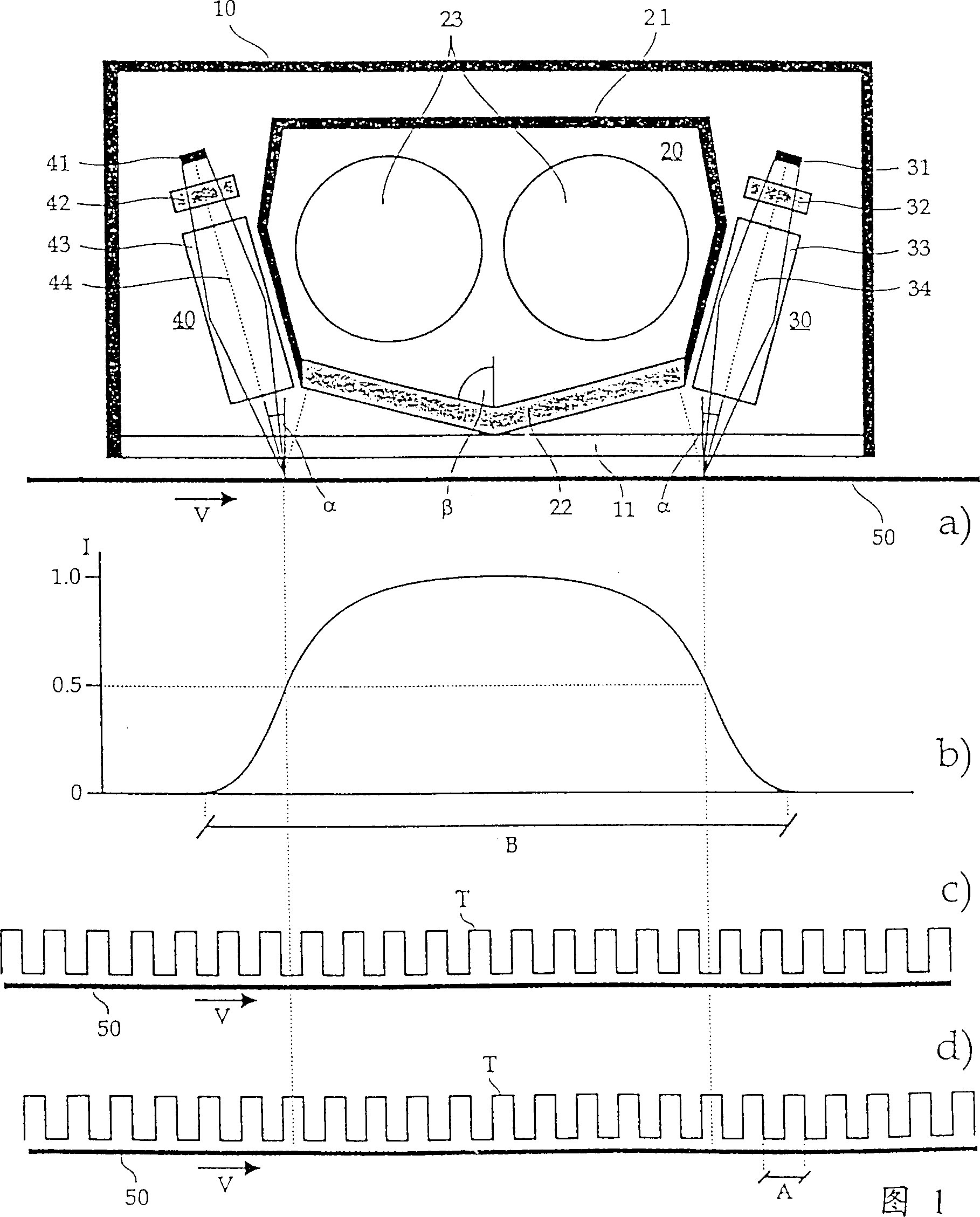
[0030] Figure 1 a shows a schematic diagram of a preferred embodiment of the apparatus according to the invention. A light-emitting device 20 and two sensors 30 and 40 are located in a light-tight housing 10 provided with a transparent window 11 . The window 11 transmits the excitation light band and the fluorescence and phosphorescence light emission bands.

[0031] The light-emitting device 20 has a light-tight housing 21, on which a filter 22 is arranged, and the filter 22 does not transmit the fluorescent and phosphorescent light-emitting bands to be detected. Arranged in the housing 21 is an activation lamp 23 which is clocked in due course by a control unit, not shown. The light emitted by the excitation lamp 23 includes at least a wavelength band necessary for excitation of fluorescence and phosphorescence.

[0032] As the excitation lamp 23, preferably a gas discharge lamp emitting at lea...


PUM


Abstract

The apparatus has an illuminating device for illuminating sheet material with clocked excitation light. Both during the light phase of clocked excitation light and during the dark phase of clocked excitation light a sensor detects an intensity of the light emitted by the sheet material in each case. In an evaluation device an intensity of fluorescently emitted light and an intensity of phosphorescently emitted light are derived from the intensities detected in the light phase and in the dark phase of clocked excitation light. In order to ensure long preillumination with high intensity, the sensor preferably detects the intensities of emitted light within, and toward the end (in the transport direction) of, the area of the sheet material illuminated by the illuminating device. Additionally the illuminated area of the sheet material is selected to be so great that it is a multiple of the desired resolution.

Description

field of invention [0001] The present invention describes a device and a method for detecting fluorescence and phosphorescence emitted from sheet-shaped materials, such as securities or bank notes. Background technique [0002] Such a device is disclosed in US-PS3473027. The apparatus described therein has a light emitting device which irradiates a sheet-form material with ultraviolet excitation light. The sheet-form material is preferably continuously irradiated with ultraviolet excitation light. Clockwise irradiation of sheet material is also possible if desired. The light emitted by the sheet material is detected by a sensor. For this purpose, a lens system is used to image the emitted light onto a prism, and then the prism decomposes the emitted light into specific wavelength bands of light. The light of each wavelength band is imaged by another lens system onto a separate detector which emits an electrical signal proportional to the intensi...

Claims


Application Information

Patent Timeline
IPC IPC(8): G01N21/64G07D7/00G07D7/12
CPCG07D7/12
Inventor 尼古莱·利普科维奇伯恩德·旺德勒海因茨-菲利普·霍荣格
Owner GIESECKE & DEVRIENT GMBH
Learn More