
Novel liquid cooling equipment case

A liquid cooler, a new type of technology, applied in the direction of cooling/ventilation/heating transformation, electrical components, electrical equipment structural parts, etc., can solve problems affecting the normal operation of electronic equipment, hidden dangers, and inability to realize the design of water and electricity separation of water circulation mechanisms , to achieve the effect of simple and reliable molding, high reliability, flexible and compact structure

Pending Publication Date: 2019-04-19
ANHUI BOWEI CHANGAN ELECTRONICS
View PDF1 Cites 7 Cited by
  • Summary
  • Abstract
  • Description
  • Claims
  • Application Information

AI Technical Summary

Problems solved by technology

[0004] In the prior art, the patent publication number: CN203812163U's Chinese utility model patent application discloses an ATR liquid-cooled reinforced computer case, and the case has announced a technical solution: a cooling channel is provided in the frame of the case, and the cooling channel is Sealed pipes, it can be seen that the cooling flow channel in the water circulation mechanism of the case is set inside the case, and the water and electricity separation design that completely separates the water circulation mechanism from the inside of the case cannot be realized. Once the cooling flow channel leaks, it will not only affect the normal operation of electronic equipment. Work, but also bring some security risks

Method used


Image

  • Novel liquid cooling equipment case
  • Novel liquid cooling equipment case
  • Novel liquid cooling equipment case

Examples


Embodiment Construction

[0040] It should be noted that, in the case of no conflict, the embodiments in the present application and the features in the embodiments can be combined with each other. The present invention will be described in detail below with reference to the accompanying drawings and examples.

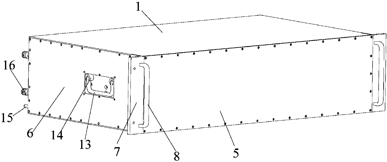
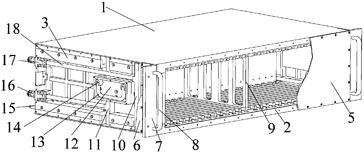
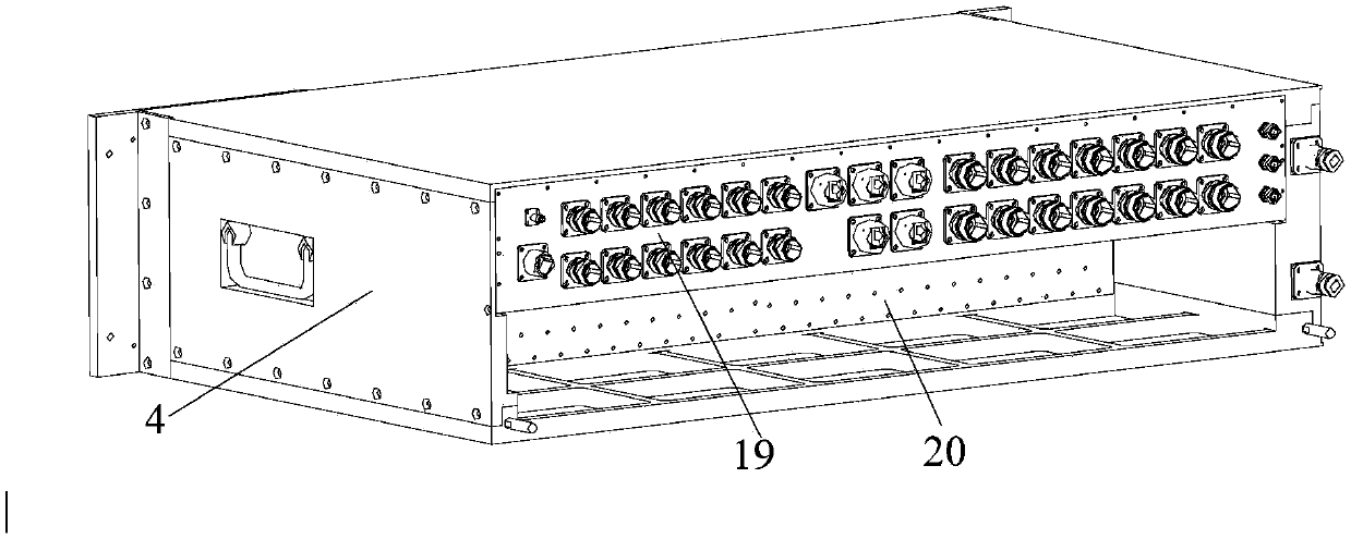
[0041] Figure 1-Figure 12 Some embodiments according to the invention are shown.

[0042] Such as Figure 1~3 As shown, a new type of liquid-cooled chassis includes: an upper cold plate 1, a lower cold plate 2, a left side plate 3, a right side plate 4, a front cover plate 5, a printed back plate 20, an adapter plate 19, a liquid-cooled Inlet pipeline 10, and liquid cooling outlet pipeline 11. Wherein, the left side plate 3, the right side plate 4, the front cover plate 5, and the upper cold plate 1 and the lower cold plate 2 are connected by captive screws, which are convenient for manual installation by hand.

[0043] Specifically, as Figure 4 , 5 , 7, the fronts of the upper cold pla...


PUM


Abstract

The invention discloses a novel liquid cooling equipment case which comprises an upper cold plate, a lower cold plate, a left side plate, a left cover plate, a right side plate, a front cover plate, aprinted back plate, and an adapter plate. The inner surfaces of the upper and lower cold plates are equipped with plug-in guide rails. The outer surfaces of the upper and lower cold plates are equipped with cooling flow passages. The novel liquid cooling equipment case further includes a liquid cooling inlet pipe and a liquid cooling outlet pipe. The liquid cold inlet pipe and the liquid coolingoutlet pipe are in sealed connection with the inlet ends of the cooling flow passages of the upper cold plate and the lower cold plate respectively. The liquid cooling inlet pipe and the liquid cooling outlet pipe are installed outside the left side plate. The left side plate is configured to spatially isolate the liquid cooling inlet pipe and liquid cooling outlet pipe from the plug-in guide rails for mounting a plug-in module. The novel liquid cooling equipment case is flexible and compact in structural form, is improved in the rigidity, environmental adaptability and heat dissipation performance, has good economical efficiency and a water and electricity separation function, reduces the risk of liquid leakage, and has an expanded application range.

Description

technical field [0001] The invention relates to the field of military airborne electronic equipment, in particular to a novel horizontal liquid-cooled chassis. Background technique [0002] With the development of microelectronics technology, airborne electronic equipment continues to develop in the direction of miniaturization, integration, and modularization, resulting in prominent heat dissipation problems. Studies have shown that more than 55% of electronic equipment failure forms are caused by excessive temperature. At present, most airborne chassis adopt forced air cooling to dissipate heat. Obviously, this method can no longer satisfy high heat density modules. Since liquid cooling is 100 to 2000 times more efficient than air cooling, liquid cooling has a great impact on electronic devices. The thermal management has a unique advantage. Therefore, vehicle-mounted radars gradually adopt liquid-cooled chassis. Through the cold plate structure, the heat inside the chas...

Claims


Application Information

Patent Timeline
Patent Type & Authority Applications(China)
IPC IPC(8): H05K7/20
CPCH05K7/20872
Inventor 盛成王磊严诺张应帅沙美妤张群
Owner ANHUI BOWEI CHANGAN ELECTRONICS
Learn More