Sleeve column feeding and pressing mechanism

A technology of press-fitting and mounting, which is applied in metal processing, metal processing equipment, manufacturing tools, etc., can solve the problems of difficult assembly of mounting rods, difficult grasping and translation of mounting rods, low assembly efficiency of mounting rods, etc., and achieves improved The degree of automation, reasonable structure design, and the effect of ensuring efficiency and quality

Inactive Publication Date: 2019-04-23
嘉兴汉羿文化传播有限公司
View PDF0 Cites 14 Cited by
  • Summary
  • Abstract
  • Description
  • Claims
  • Application Information

AI Technical Summary

Problems solved by technology

The existing workpiece assembly is difficult to efficiently and smoothly realize the continuous assembly of the workpiece, especially for the column workpiece with a cylindrical structure. Due to the circular structure, the column is difficult to be grasped and translated conveniently and smoothly. Therefore, no matter the assembly of the column workpiece The previous loading and the whereabouts of the column workpiece after assembly require workers to manually operate the workpiece, which reduces the automation of the assembly of the column workpiece, and it is difficult for the existing column workpiece to meet the synchronization and stability of multiple column workpieces during the assembly process. assembly, the assembly efficiency of the sleeve workpiece is low, which cannot meet the needs of processing and use

Method used


Image

  • Sleeve column feeding and pressing mechanism
  • Sleeve column feeding and pressing mechanism
  • Sleeve column feeding and pressing mechanism

Examples


Embodiment Construction

[0016] In order to further describe the present invention, the specific implementation of a bushing column feeding and pressing mechanism will be further described below in conjunction with the accompanying drawings. The following examples are explanations of the present invention and the present invention is not limited to the following examples.

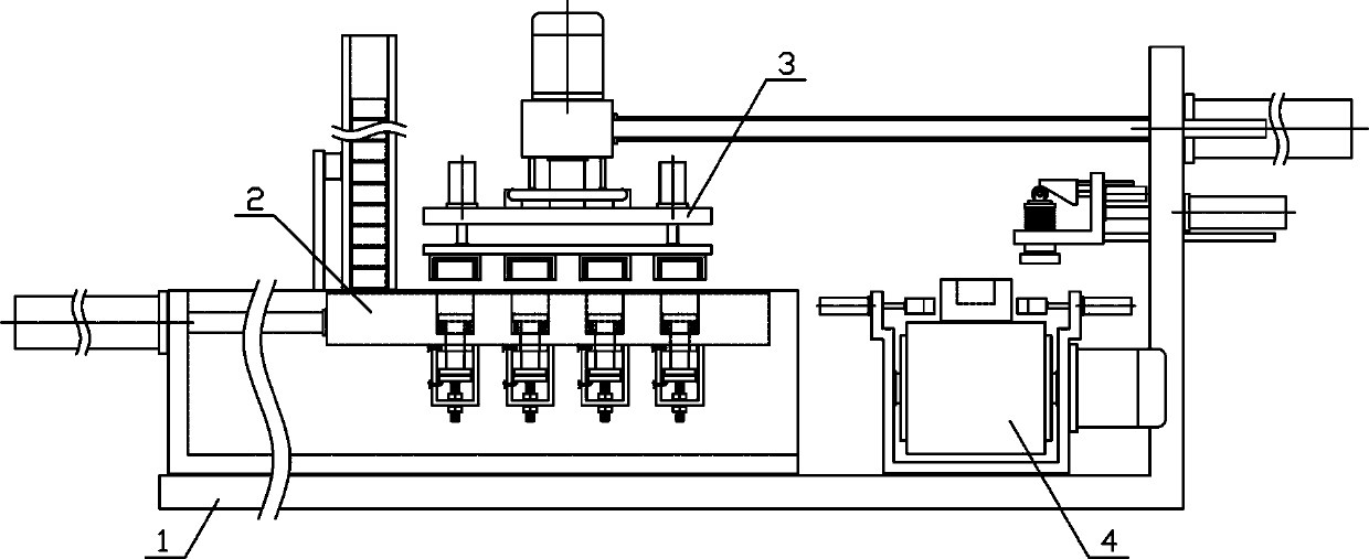
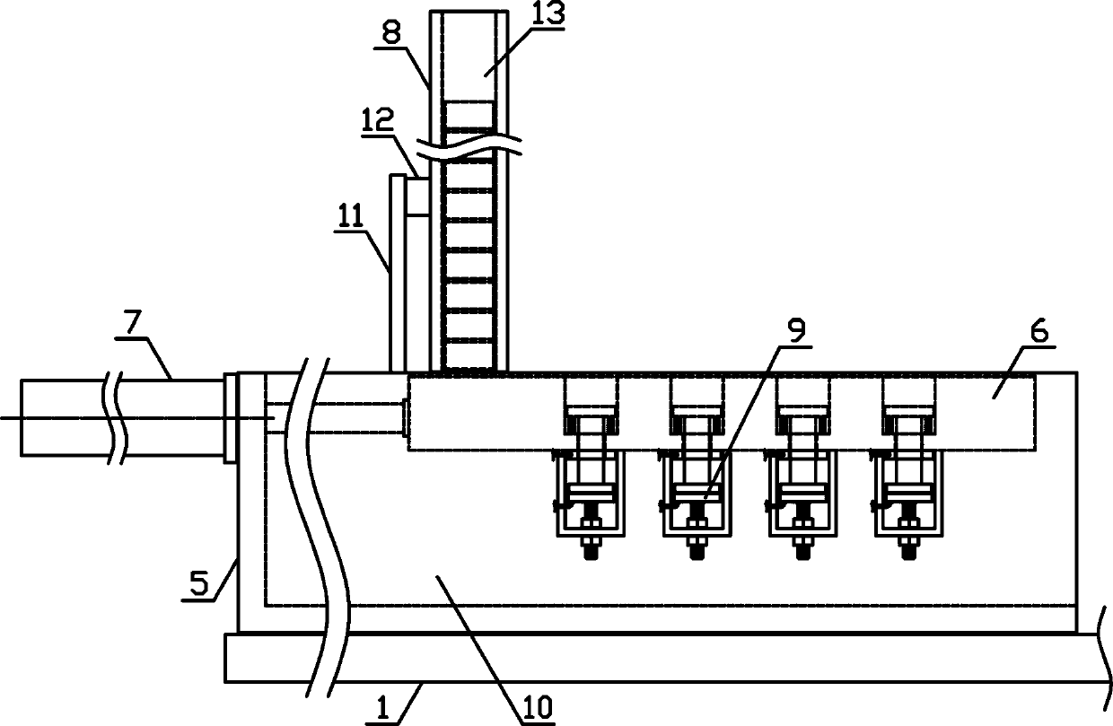
[0017] like figure 1 As shown, a column feeding and pressing mechanism of the present invention includes a fixed bracket 1, a material guiding mechanism 2, a feeding mechanism 3 and a pressing mechanism 4, and the material guiding mechanism 2 and the pressing mechanism 3 are horizontally arranged in sequence along the horizontal direction On both sides above the fixed bracket 1 , the feeding mechanism 3 is horizontally arranged on the fixed bracket 1 on the upper side of the pressing mechanism 4 . like figure 2 As shown, the material guide mechanism 2 of the present invention includes a push plate support 5, a material guide conn...


PUM


Abstract

The invention discloses a sleeve column feeding and pressing mechanism and belongs to the field of mechanical assembling equipment for workpieces. In the sleeve column feeding and pressing mechanism disclosed by the invention, a guide mechanism and a pressing mechanism are sequentially and horizontally arranged in the horizontal direction and at the two sides of the upper portion of a fixing bracket; a feeding mechanism is horizontally arranged at the fixing bracket is positioned at the upper side of the pressing mechanism; a material guide connecting plate is sequentially and vertically provided with a plurality of bearing mechanisms in the horizontal direction; the output end of a feeding cylinder is fixedly connected with the middle part of one side of a feeding guide plate; a rotary connecting plate is horizontally arranged at the lower side of the feeding guide plate; the middle part of the upper side of the rotary connecting plate is fixedly connected with the lower end of a feeding rotating shaft; an adsorbing connecting plate is horizontally arranged at the lower side of the rotary connecting plate; a conveying belt is horizontally arranged at the upper side of a conveyingbracket; the output end of a translating cylinder is horizontally and fixedly provided with a pressing bracket; and the pressing bracket is vertically and slidably provided with a pressing guide rod.The sleeve column feeding and pressing mechanism disclosed by the invention is reasonable in structural design, can be used for synchronously and stably adsorbing and feeding a plurality of sleeve columns and synchronously and efficiently pressing and assembling a plurality of sleeve columns, and meets the requirements of production and application.

Description

technical field [0001] The invention belongs to the field of workpiece assembling machinery and equipment, and in particular relates to a column feeding and pressing mechanism, which is mainly applied to the continuous translation assembly of column workpieces. Background technique [0002] The mechanical workpiece is a single piece that makes up the machine and its inseparability. It plays an important role in the automation industry. The mechanical workpiece includes the connection of parts, the supporting parts, the lubricating lubrication system and the sealing Components, components of the transmission system that transmit motion and energy. In the process of producing and processing mechanical workpieces, after the workpieces undergo processing steps such as die-casting, grinding, and drilling, the individually processed workpieces need to be Assemble, assemble two workpieces into a combined workpiece, so that the assembled workpieces can be conveniently used by subseq...

Claims


Application Information

Patent Timeline
Patent Type & Authority Applications(China)
IPC IPC(8): B23P19/027
CPCB23P19/027B23P19/001B23P19/006
Inventor 王英
Owner 嘉兴汉羿文化传播有限公司
Why Eureka
Try Eureka