

Low temperature vessel
A technology of cryogenic container and outer shell, which is applied to pressure container, container filling method, outer wall of container structure, etc. Strength and effect of increasing piping space
- Summary
- Abstract
- Description
- Claims
- Application Information
AI Technical Summary
Problems solved by technology
Method used
Image

Examples
Embodiment 1
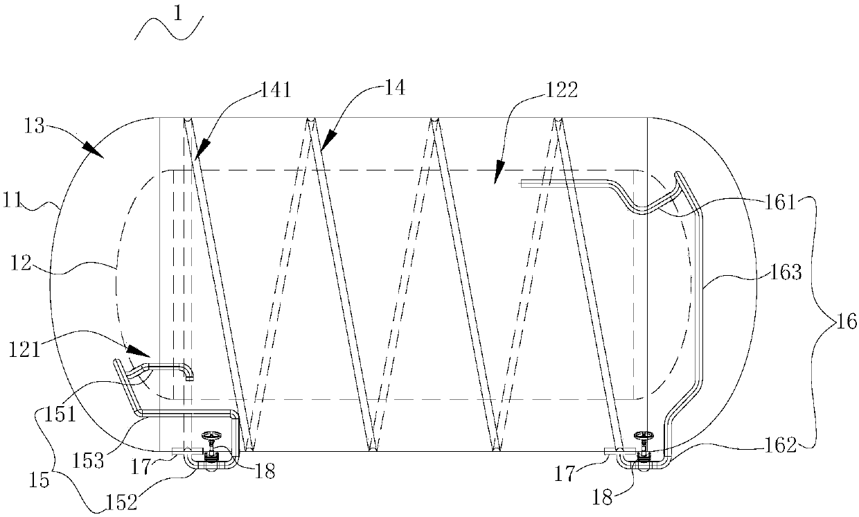
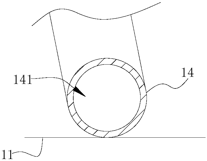
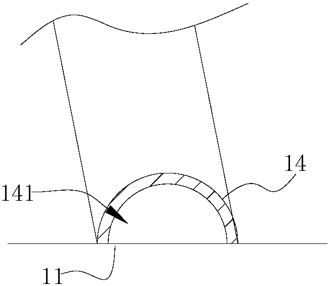
[0026] refer to figure 1 , the present embodiment provides a low-temperature container 1, including an outer shell 11 and an inner tank 12 arranged inside the outer shell 11, the inner tank 12 is used to hold a low-temperature medium, and an interlayer is also provided between the outer shell 11 and the inner tank 12 13. Further, the cryogenic container 1 of this embodiment further includes a pressurized passage 14, and the pressurized passage 14 includes a hollow medium channel 141 for the circulation of the medium.
[0027] Specifically, the pressurization passage 14 of this embodiment is connected to the outer shell 11 , and the pressurization passage 14 surrounds the outer shell 11 in the circumferential direction and is distributed along the axial direction of the outer shell 11 . In this embodiment, the inlet of the medium channel 141 communicates with the liquid phase space 121 of the inner tank 12 , and the outlet of the medium channel 141 communicates with the gas ph...
Embodiment 2
[0044] refer to image 3 , the structure of the cryogenic container 1 in this embodiment is substantially the same as that of Embodiment 1, the main difference is that: the pressurization passage 14 of this embodiment includes a plurality of annular passages 142 surrounding the circumference of the outer shell 11, and a plurality of The annular passages 142 are arranged at intervals along the axial direction of the outer casing 11 , and a connecting passage 143 is provided between two adjacent annular passages 142 , so that the plurality of annular passages 142 communicate with each other.
[0045] Further, in this embodiment, the outer liquid pipe 152 communicates with the annular passage 142 close to the liquid phase space 121 of the inner tank 12, and the outer air pipe 162 communicates with the annular passage 142 near the gas phase space 122 of the inner tank, thereby reducing pipeline The length of the layout reduces production costs.
[0046] In summary, the low-temper...
PUM
 Abstract
Description
Claims
Application Information