

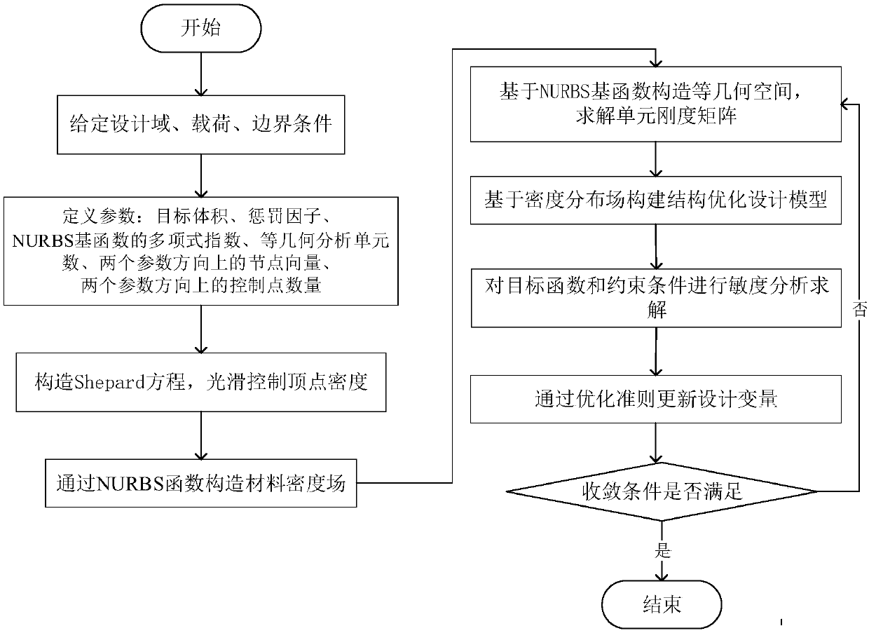
Isogeometric material density field structure topology optimization method
A material density and topology optimization technology, applied in design optimization/simulation, instrumentation, calculation, etc., can solve problems such as checkerboard problems, non-smooth local minima, and achieve efficiency improvement, error elimination, and adaptability
- Summary
- Abstract
- Description
- Claims
- Application Information
AI Technical Summary
Problems solved by technology
Method used
Image

Examples
example 1
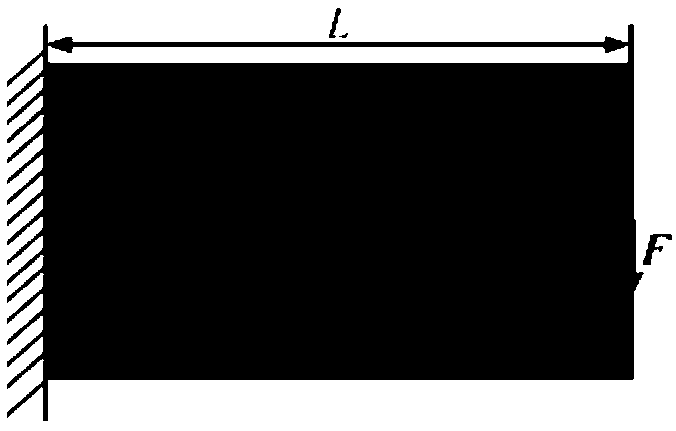
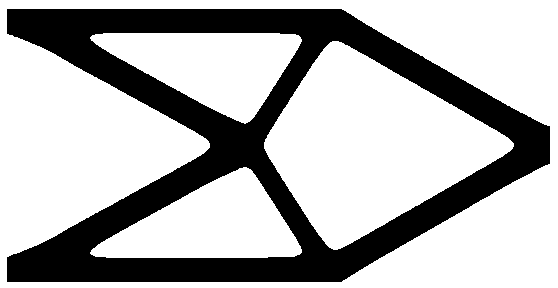
[0073] Example 1, please refer to Figure 2~4
[0074] (1) if figure 2 As shown, the design domain is a cantilever beam structure with L=10, H=5, the left boundary is fixed, and there is a concentrated load F=1 at the middle point of the right boundary.
[0075] (2) Define the parameters as follows: target volume 30%, penalty factor 3, polynomial exponent of NURBS basis function 3, isogeometric analysis grid contains 100×50 elements, two parameter directions ξ, node vectors on η respectively For: Ξ={0, 0, 0, 0, 0.01, ..., 0.99, 1, 1, 1, 1} and The numbers of control vertices on the parameter directions ξ and η are respectively n=103 and m=53.
[0076] (3) Use the Shepard function to smooth the control vertex density, and the smoothed control vertex density can be expressed as:
[0077]
[0078] In the formula, is the smoothed density of control vertex (i, j), ρ i,j Indicates the density at the control vertex (i, j), w(ρ i,j) represents the weight at the control ve...
example 2
[0104] Instance 2, please refer to Figure 5-7
[0105] Figure 5 Take a 1 / 4 ring structure with an outer diameter of R=10 and an inner diameter of r=5 as an example. It is fixed at the vertex of the upper left corner, and a downward force F=1 is applied, and the lower right edge is slidably fixed. The degree of the NURBS basis function is 3. The node vectors of the two parameter directions are: Ξ={0, 0, 0, 0, 0.01, ..., 0.99, 1, 1, 1, 1} and The corresponding isogeometric grid contains 100×50 cells. The number of control points in the two parameter directions is 103×53, the number of design variables is 5459, and the maximum target volume fraction V 0 40%. The total compliance value obtained by final optimization is 110.39.
[0106] The optimization process of Example 2 is the same as that of Example 1. Figure 6 In order to optimize the results, it is not difficult to see that the optimization of the curve boundary also has a good effect, Figure 7 is the iterative ...
PUM
 Abstract
Description
Claims
Application Information