Rotor double-winding pole-changing asynchronous starting vernier motor

A technology for asynchronous starting and vernier motors, which is applied to the rotating parts of the magnetic circuit, the shape/style/structure of winding conductors, and electromechanical devices, etc. It can solve the problems that the starting performance and steady-state performance of asynchronous starting vernier motors cannot be balanced, and achieve Increased torque density, high efficiency, and steady-state performance

Active Publication Date: 2019-04-23
HUAZHONG UNIV OF SCI & TECH
6 Cites 2 Cited by

AI-Extracted Technical Summary

Problems solved by technology

[0004] In view of the above defects or improvement needs of the prior art, the present invention provides a pole-changing asynchronous starter vernier motor with doubl...

Abstract

The invention discloses a rotor double-winding pole-changing asynchronous starting vernier motor which comprises a stator and a rotor. The stator comprises a stator core and stator windings. The rotorcomprises a rotor core, rotor damping windings, rotor starting windings and permanent magnets. The stator iron core is annular, and the inner ring surface of the stator iron core is provided with a plurality of open slots used as stator slots along the circumferential direction and used for accommodating stator windings. The rotor iron core is coaxially sleeved with the stator iron core. A plurality of rotor grooves are formed in the outer surface, opposite to the inner ring surface of the stator iron core, of the rotor iron core in the circumferential direction. The tops of the rotor groovesare used for containing rotor damping windings, and the bottoms of the rotor grooves are used for containing rotor starting windings. The plurality of permanent magnets are arranged in the rotor ironcore. According to the rotor double-winding variable-pole asynchronous starting vernier motor provided by the invention, the double-winding rotor is adopted, and a pole changing mode is utilized. Therefore, the electromagnetic torque exceeding a common asynchronous starting permanent magnet motor is output during steady-state operation. Meanwhile, the starting performance can be ensured, and thesteady-state performance can be also considered.

Application Domain

Magnetic circuit rotating partsMagnetic circuit stationary parts +1

Technology Topic

PhysicsElectromagnetic torque +2

Image

  • Rotor double-winding pole-changing asynchronous starting vernier motor
  • Rotor double-winding pole-changing asynchronous starting vernier motor

Examples

  • Experimental program(1)

Example Embodiment

[0021] In order to make the objectives, technical solutions and advantages of the present invention clearer, the following further describes the present invention in detail with reference to the accompanying drawings and embodiments. It should be understood that the specific embodiments described herein are only used to explain the present invention, but not to limit the present invention.
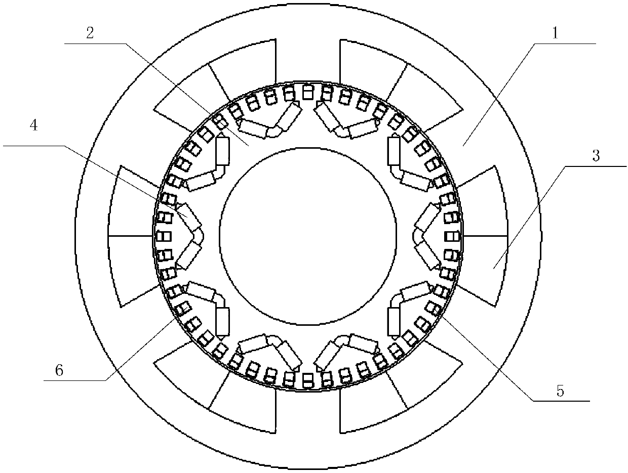
[0022] The invention provides a pole-changing asynchronous start vernier motor with dual rotor windings, such as figure 1 As shown, it includes a stator and a rotor; where the stator includes a stator core 1 and a stator winding 3, and the rotor includes a rotor core 2, a rotor damper winding 5, a rotor start winding 6 and a permanent magnet 4.
[0023] The stator core 1 is ring-shaped, and its inner ring surface is provided with a plurality of opening slots as stator slots along the circumferential direction to accommodate the stator winding 3; the rotor core 2 is coaxially sleeved in the stator core 1, and is opposite to the stator core The outer surface of the inner ring surface of the core 1 is provided with a plurality of rotor slots along the circumferential direction. The top of the rotor slot is used to accommodate the rotor damper winding 5, and the bottom of the rotor slot is used to accommodate the rotor start winding 6; a plurality of permanent magnets 4 are arranged in the rotor core 2 .
[0024] The stator winding 3 is a pole-changing single winding with a bipolar number, and the rotor damper winding 5 and the rotor starting winding 6 are wound double windings.
[0025] Specifically, the number of pole pairs of the rotor starting winding is the same as the number of stator winding pole pairs when the stator is started, and the number of pole pairs of the rotor damper winding is the same as the number of permanent magnet pole pairs.
[0026] Specifically, when the number of stator slots is greater than the number of permanent magnet pole pairs, the sum of the number of pole pairs of the stator winding and the number of permanent magnet pole pairs is the number of stator slots; when the number of stator slots is less than the number of permanent magnet pole pairs, the stator winding The sum of the number of pole pairs and the number of stator slots is the number of permanent magnet pole pairs.
[0027] Specifically, the number of pole pairs when the stator winding is started is less than the number of pole pairs during normal operation, and the number of pole pairs when the stator winding is normal is less than the number of permanent magnet pole pairs.
[0028] Specifically, the permanent magnet may be a surface mount type or a built-in type, that is, a common straight-shaped, V-shaped, W-shaped, or Spoke-shaped. In this embodiment, the permanent magnet adopts a V-shaped built-in type.
[0029] Specifically, there are multiple stator slots, which are evenly distributed along the circumferential direction of the inner ring surface of the stator iron core; and the rotor slots are multiple, and are evenly distributed along the circumferential direction of the inner ring surface of the rotor iron core.
[0030] When the stator winding changes poles during starting, the number of pole pairs is different from the number of pole pairs in steady state. In order to ensure that positive starting torque can always be provided throughout the starting interval, the number of pole pairs during starting should be less than the number of permanent magnet pole pairs Pe In the asynchronous starting vernier motor in this embodiment, the number of stator slots N is 6 and the number of permanent magnet pole pairs Pe is 5. Then the number of pole pairs Pa of the stator winding in the steady state is 1, and the number of stator pole pairs is 2 when starting. , The number of pole pairs of the rotor starting winding is 2, and the number of pole pairs of the rotor damping winding is 5. The winding connection is as figure 2 Shown. When starting, switch S2 is closed and S1 is opened. At this time, the number of pole pairs of the stator winding is 2, which is lower than the number of permanent magnets of 5, and the number of pole pairs of the rotor starting winding is 2, and the two sets of windings interact to start. When the steady-state synchronous speed is near, S1 is opened and S2 is closed. At this time, the number of pole pairs of the stator winding is 1, which satisfies Pa=|N±Pe|, the synchronous speed is 60f/Pe in the steady state, and the number of pole pairs of the rotor damper winding It can play a damping role for Pe, and the hourly speed is stable at the synchronous speed.
[0031] Those skilled in the art can easily understand that the above descriptions are only preferred embodiments of the present invention and are not intended to limit the present invention. Any modification, equivalent replacement and improvement, etc. made within the spirit and principle of the present invention, All should be included in the protection scope of the present invention.

PUM

no PUM

Description & Claims & Application Information

We can also present the details of the Description, Claims and Application information to help users get a comprehensive understanding of the technical details of the patent, such as background art, summary of invention, brief description of drawings, description of embodiments, and other original content. On the other hand, users can also determine the specific scope of protection of the technology through the list of claims; as well as understand the changes in the life cycle of the technology with the presentation of the patent timeline. Login to view more.

Similar technology patents

Magnetically guided catheter

ActiveUS20100174177A1low costhigh performance
Owner:ST JUDE MEDICAL ATRIAL FIBRILLATION DIV

Material including graphene and an inorganic material and method of manufacturing the material

ActiveUS20110129675A1reduce defectlow cost
Owner:SAMSUNG ELECTRONICS CO LTD +1
Why Eureka
Try Eureka