Fuel supply control system for engine

A technology of fuel supply and control system, applied in the direction of charging system, engine components, machine/engine, etc., to ensure the starting performance and prevent shrinkage and deformation.

Inactive Publication Date: 2005-02-16
HONDA MOTOR CO LTD
View PDF1 Cites 1 Cited by
  • Summary
  • Abstract
  • Description
  • Claims
  • Application Information

AI Technical Summary

Problems solved by technology

[0003] With this conventional engine fuel supply control system, when the engine operation is stopped, the automatic fuel valve can prohibit the fuel from flowing down from the fuel tank to the fuel supply part in the engine, but the upper space in the fuel tank is in such a state that it passes through The vent is open to the atmosphere, so if vaporized fuel is produced in the tank, it is vented to the atmosphere through the vent

Method used


Image

  • Fuel supply control system for engine
  • Fuel supply control system for engine
  • Fuel supply control system for engine

Examples


Embodiment Construction

[0036] The present invention will now be described by way of preferred embodiments with reference to the accompanying drawings.

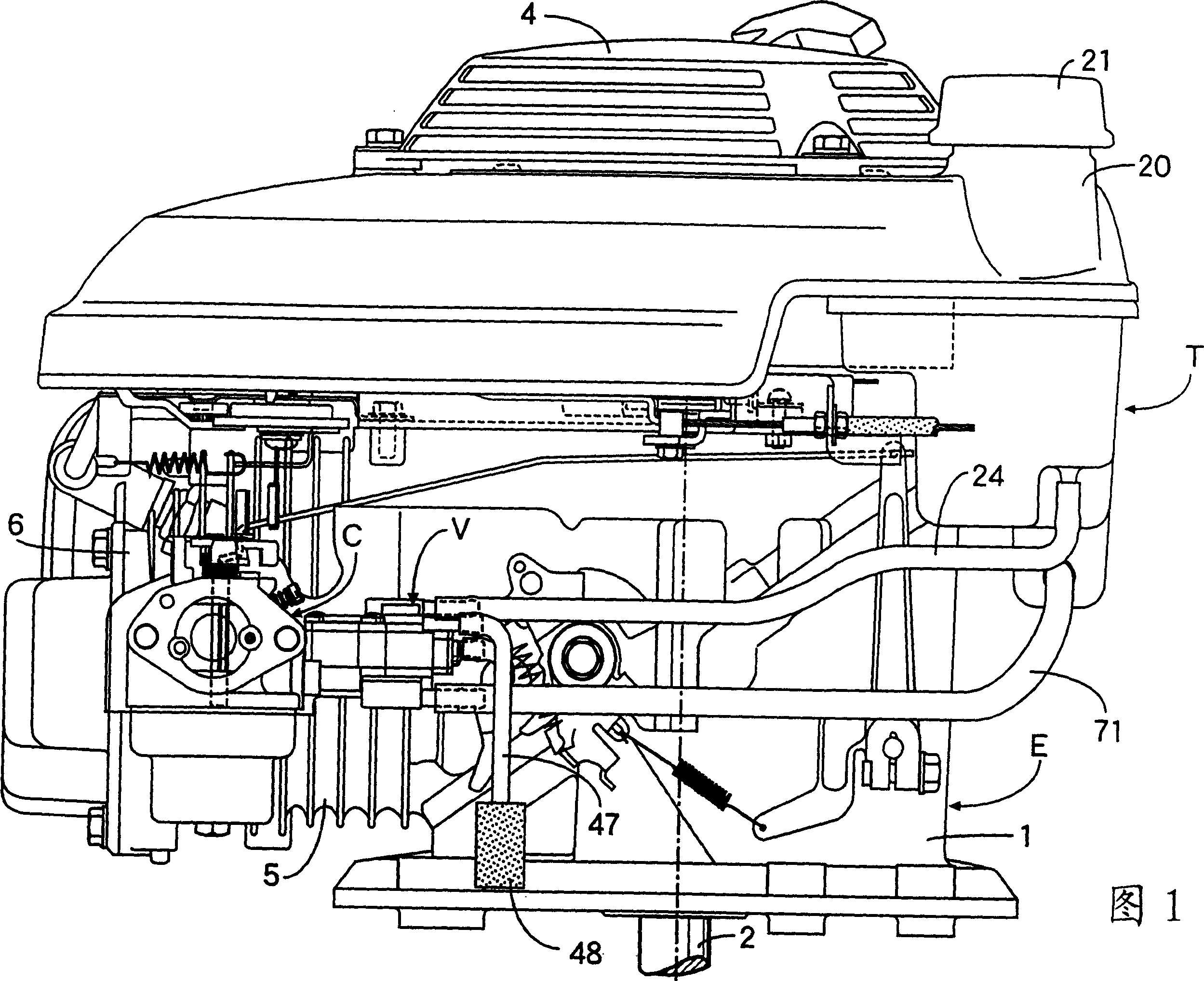
[0037] First, a first embodiment of the present invention shown in FIGS. 1-11 will be described. In FIGS. 1 and 2, reference numeral E denotes a 4-stroke vertical type general-purpose engine. The crankshaft 2 supported in the crankcase 1 of the engine E is arranged vertically, and its output end protrudes downward to the bottom of the crankcase 1 . A fuel tank T and a recoil starter 4 are attached to the upper portion of the crankcase 1 .

[0038] A cylinder block 5 having a horizontally arranged cylinder axis is connected to one side of the crankcase 1 , and a carburetor C is mounted to one side of a cylinder head 6 coupled to an end of the cylinder block 5 .

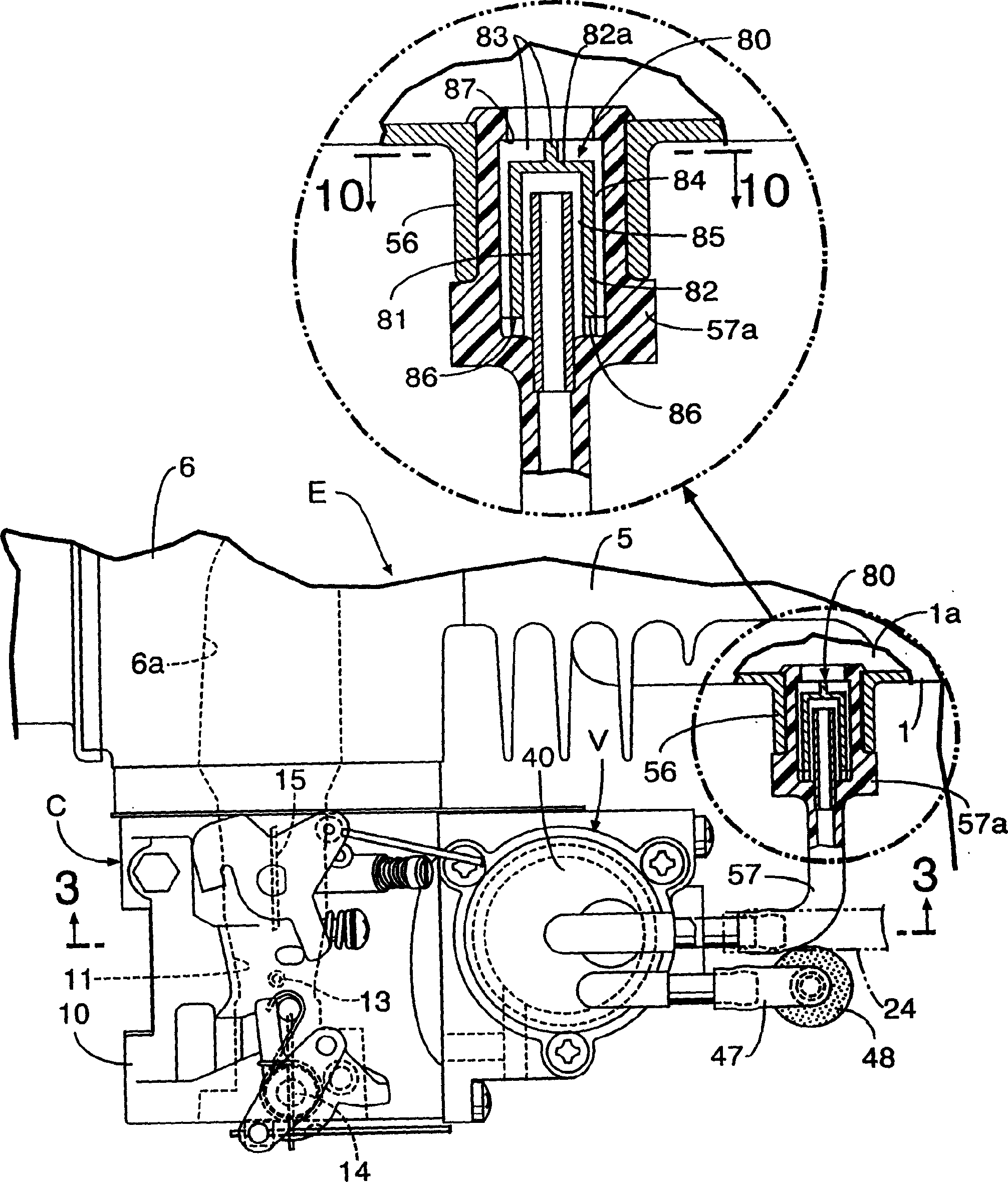
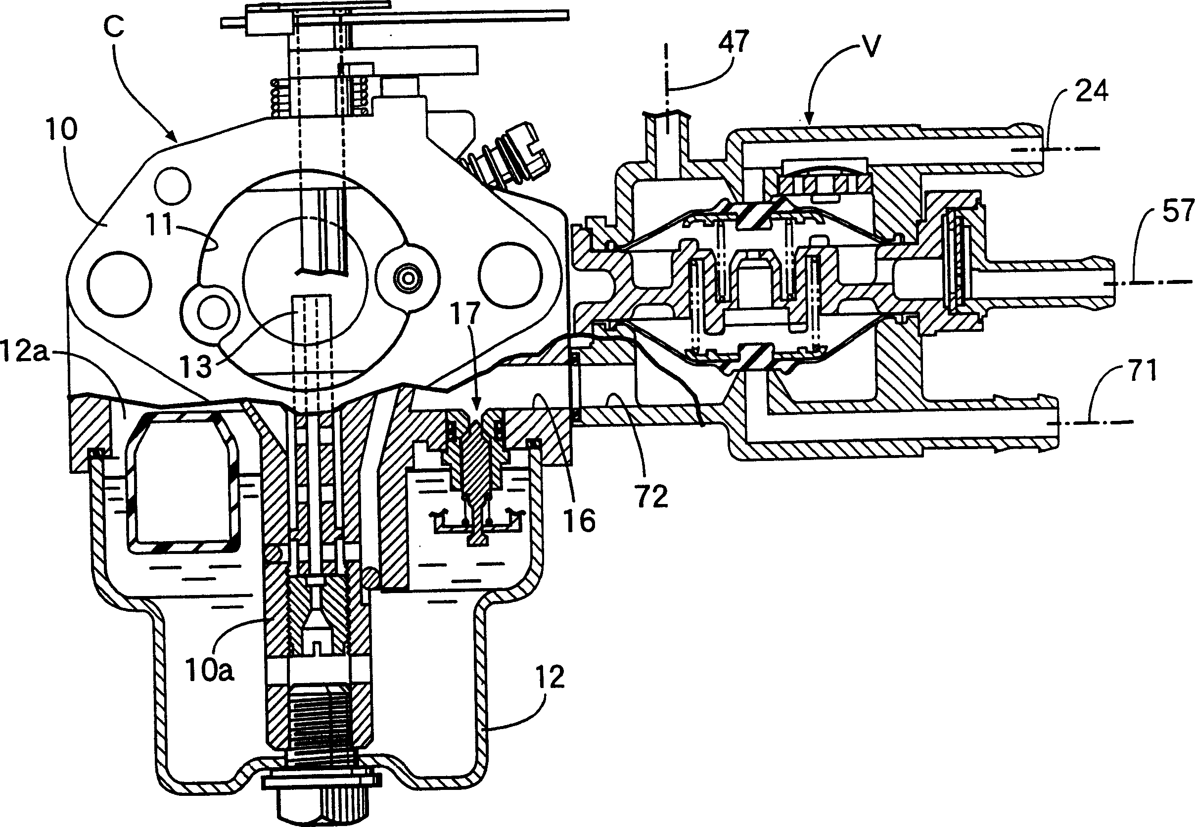
[0039] refer to image 3, the carburetor C includes: a carburetor body 10, which has an air intake passage 11 leading to the air intake port 6a of the cylinder head 6; a floating chamber ...


PUM


Abstract

A composite control valve is constructed by a valve housing, first and second diaphragms mounted to the valve housing and disposed to be opposed to each other, a negative pressure working chamber defined between the first and second diaphragms to communicate with a negative pressure generating section in an engine, a first control valve adapted to be opened and closed by advancing and returning of the first diaphragm, and a second control valve adapted to be opened and closed by advancing and returning of the second diaphragm. The first control valve is incorporated into an air vent system for a fuel tank, and the second control valve is incorporated into a fuel passage system extending from the fuel tank to a fuel supply section in the engine. Thus, upon stoppage of the operation of the engine, not only the fuel passage system but also the air vent system leading to the upper space in the fuel tank are blocked simultaneously, thereby preventing release of an evaporated fuel generated in the fuel tank to the atmosphere.

Description

technical field [0001] The invention relates to a fuel supply control system for an engine for controlling the opening and closing of a vent system which communicates the upper space of the fuel tank with the atmosphere and for controlling the opening and closing of a fuel channel system which will be located below the surface of the fuel oil A portion of the fuel tank communicates with the fuel supply within the engine. Background technique [0002] Japanese Utility Model Application Laid-Open No. 62-93145 discloses a conventional engine fuel supply control system in which a negative pressure responsive type automatic fuel that is opened by negative pressure generated by a negative pressure generating part inside the engine is suitable. The switch is installed in the fuel passage, which communicates a part of the fuel tank below the fuel level with the fuel supply part in the engine, so that when the engine stops, the fuel passage is automatically closed by the automatic fu...

Claims


Application Information

Patent Timeline
IPC IPC(8): F02M17/04F02M25/08F02M37/20
CPCF02M37/20F02M17/04F02M25/0836
Inventor 山田义和宇津木英一千叶省作佐佐木勉筒井胜彦
Owner HONDA MOTOR CO LTD
Why Eureka
Try Eureka