Lathe capable of realizing positioned cutting

A lathe and fixed block technology, which is applied to large fixed members, automatic control devices, feeding devices, etc., can solve problems such as cumbersome operations, and achieve the effect of simplifying adjustment operations, ensuring processing dimensions, and avoiding knife collisions.

Active Publication Date: 2019-04-26
浙江陀曼云计算有限公司
View PDF8 Cites 2 Cited by
  • Summary
  • Abstract
  • Description
  • Claims
  • Application Information

AI Technical Summary

Problems solved by technology

[0004] In order to solve the cumbersome problem of adjusting the position of the backing when the workpiece is replaced or the feed rate is replaced in the prior art, the embodiment of the present invention provides a lathe for positioning cutting, including a slide plate and a slide plate mounted on the slide plate. A moving assembly carrying a tool holder, the moving assembly includes a sliding base, a limit mechanism, and a limiter assembly, the sliding base is slidably mounted on the slide plate, the limiter assembly includes a sensor assembly, and the sensor assembly Installed on the sliding base, a fixed block is fixed on the sliding plate, and when the sliding base moves on the sliding plate, the sensor assembly is away from or close to the fixed block, wherein:

Method used


Image

  • Lathe capable of realizing positioned cutting
  • Lathe capable of realizing positioned cutting
  • Lathe capable of realizing positioned cutting

Examples


Embodiment Construction

[0034] Embodiments of the present invention are described in detail below, examples of which are shown in the drawings, wherein the same or similar reference numerals designate the same or similar elements or elements having the same or similar functions throughout. The embodiments described below by referring to the figures are exemplary only for explaining the present invention and should not be construed as limiting the present invention. On the contrary, the embodiments of the present invention include all changes, modifications and equivalents coming within the spirit and scope of the appended claims.

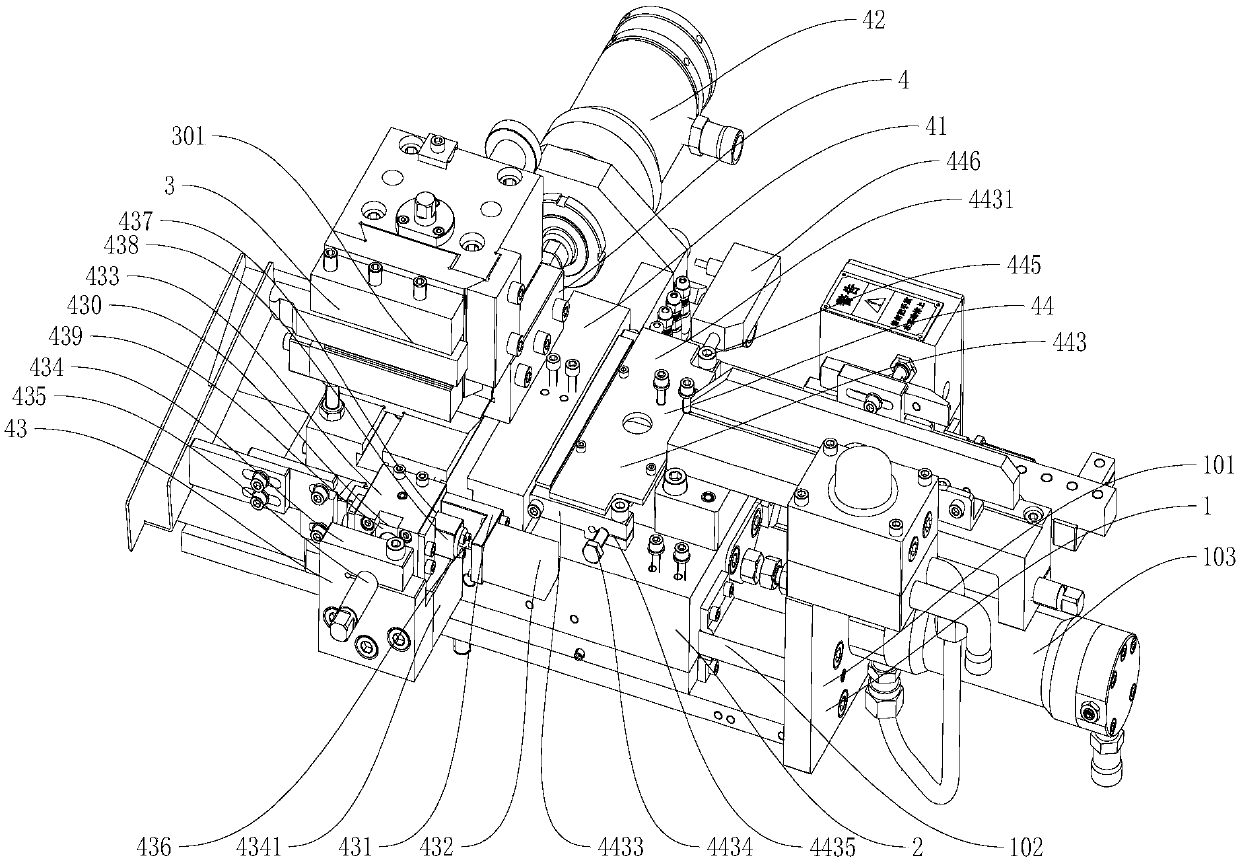
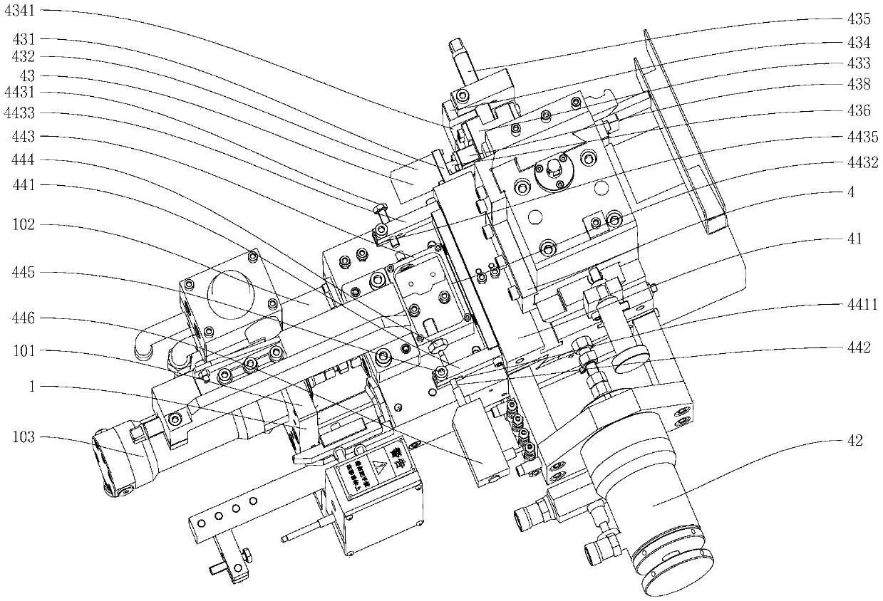
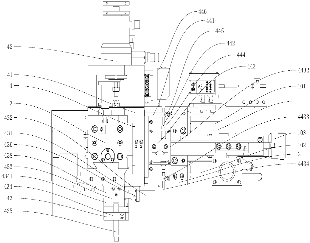
[0035] Such as Figure 1 to Figure 3 As shown, the present invention provides a lathe for positioning cutting, including a machine body 1, a slide plate 2 that moves directionally on the machine body 1, and a tool rest 3 that is movably installed on the slide plate 2, and a moving assembly 4 is fixedly installed on the bottom of the tool rest 3 , the moving assembly 4 is ...


PUM


Abstract

The invention provides a lathe capable of realizing positioned cutting. The lathe comprises a slide plate and a movable assembly which is mounted on the slide plate for bearing a tool rest, wherein the movable assembly comprises a slide base, a limiting mechanism and a limiting assembly; the slide base can be mounted on the slide plate in a sliding mode; a sensor assembly is mounted on the slide base; a fixed block is fixedly arranged on the slide plate; when the slide base moves on the slide plate, the sensor assembly gets away from or gets close to the fixed block; in a process of controlling the slide base to move towards the limiting mechanism by a controller in a lathe, a first detected value of the sensor assembly is obtained, and the first detected value is used for indicating a distance between the fixed block and the sensor assembly; and when the first detected value of the sensor assembly reaches a preset value, the slide base is controlled to switch a moving direction of theslide base, so that the slide base is far away from the limiting mechanism. The problem that operation of regulating the position of a dead corner is complex when a to-be-processed part is replaced or feeding amount is replaced in the related technologies is solved.

Description

technical field [0001] The invention relates to the technical field of lathe processing, in particular to a lathe for positioning cutting. Background technique [0002] Bearings are an important part of contemporary mechanical equipment. During the production process of bearings, the inner and outer rings of bearings need to be processed. When machining the inner and outer rings of the bearing, the bearing to be processed needs to be installed on a lathe for rotation, and the turning tool is fed longitudinally to turn the bearing to be processed during the rotation of the bearing to be processed. [0003] At present, when using a lathe for turning, the feed rate of the turning tool is mainly manually operated, and the turning tool is manually operated to feed until the installation base of the turning tool is against the dead backing to complete the turning; when the workpiece to be processed is replaced or the feed rate When replacing, the position of the backing needs to ...

Claims


Application Information

Patent Timeline
Patent Type & Authority Applications(China)
IPC IPC(8): B23Q1/25B23Q1/56B23Q5/26B23Q15/013
CPCB23Q1/25B23Q1/56B23Q5/26B23Q15/013
Inventor 俞朝杰章跃军赵传武
Owner 浙江陀曼云计算有限公司
Why Eureka
Try Eureka