Glass fiber pipe production device

A production device and glass fiber technology, applied in the field of glass fiber pipe production devices, can solve the problems of increasing the probability of pipe breakage, safety accidents, poor toughness, etc.

Pending Publication Date: 2019-04-26
江苏华盟新型材料科技有限公司
View PDF0 Cites 10 Cited by
  • Summary
  • Abstract
  • Description
  • Claims
  • Application Information

AI Technical Summary

Problems solved by technology

[0002] Many underground or ground pipes, including large water pipes, sewage pipes, oil pipelines, gas pipelines, etc., are mostly made of plastic with low strength; However, the weight is too large, the transportation and installation are difficult, the toughness is poor, and it is easy to collide and break. Once an important pipeline breaks, it will not only cause energy loss, but also cause safety accidents.
[0003] Now many manufacturers use glass fiber mixed raw materials to make pipes, and the materials used are different, resulting in different support strength and weight. For example, the existing glass fiber plastic pipes generally have weak strength and toughness, which increases the risk of pipe fracture probability, which reduces the stability of the pipes during use, and the curing time of the devices used in the production process of these pipes is relatively long, which is not suitable for the requirements of rapid production

Method used


Image

  • Glass fiber pipe production device
  • Glass fiber pipe production device
  • Glass fiber pipe production device

Examples


Embodiment approach 1

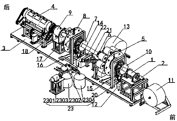
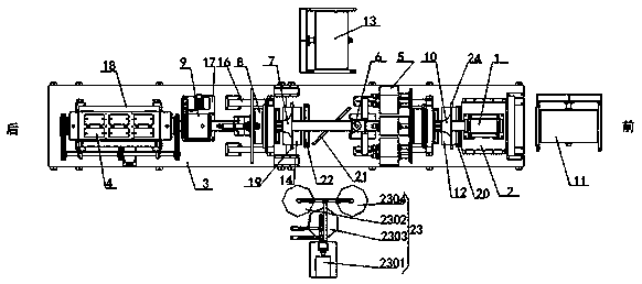
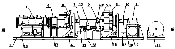
[0056] This embodiment provides a glass fiber pipe production device, such as Figures 1 to 3 , as shown, the mandrel 1 is horizontally fixed on the frame 3 through the first bracket 2, and the wrapping cloth frame 11 and the tractor (not shown in the figure) are both fixed on the frame 3 and are respectively located at the front end and the At the end, along the axial direction of the core mold 1, there are sequentially arranged a first wrapping plate 10, a winding yarn assembly 5, a fixed sizing box 6, a second wrapping plate 7, a wrapping cloth assembly 8, a rotating sizing assembly 9 and a forming furnace assembly 4. The first glue box 12 is fixed on the frame 3 and is located between the wrapping cloth frame 11 and the winding yarn assembly 5. A first radial guide shaft 24 is installed in the first glue box 12. Between the wrapping cloth frame 11 and the second Between the plastic boxes 12, there is also a material passing wheel 20 fixed on the first support 2; the fiber ...

Embodiment approach 2

[0067] This embodiment is a further improvement of Embodiment 1. The main improvement is that, in Embodiment 1, the angle at which the wrapping cloth in the wrapping cloth frame 808 is wound onto the mandrel 1 cannot be adjusted, while the wrapping cloth is wound onto the mandrel. The angle on 1 directly affects the strength and toughness of the final glass fiber pipe, so the production device of the glass fiber pipe in embodiment 1 cannot be adjusted according to the needs of product performance, and the scope of application is narrow. In this embodiment, the angle at which the wrapping cloth is wound onto the mandrel 1 can be adjusted, so that the glass fiber pipe production device in this embodiment can be adjusted accordingly according to the product performance, and the scope of application is wider.

[0068] Specifically, in this embodiment, the wrapping cloth assembly 8 also includes an angle adjustment mechanism connected to the front end of the third bearing seat 810 t...

Embodiment approach 3

[0071] This embodiment is a further improvement of Embodiment 2. The main improvement is that in Embodiment 2, during the gluing process of the rotary gluing assembly 9, uneven gluing often occurs and excess glue cannot be discharged from the rotating drum. In some cases, the surface of the final fiberglass pipe is not smooth, and the quality of the glass fiber cannot meet the requirements. However, in this embodiment, the above defects can be effectively avoided, the gluing in the rotary gluing assembly 9 can be made uniform, and excess glue can be effectively discharged from the rotary drum 903 .

[0072] Specifically, in this embodiment, as Figure 18 A screw groove 909 with a preset length is provided on the inner wall of the end of the rotary cylinder 903 in the rotary glue application assembly 9. The beginning of the screw groove 909 is located at the rear side of the glue injection hole 907, and the thread of the screw groove 910 is from the beginning to the end. The d...


PUM


Abstract

The invention relates to the field of glass fiber pipe manufacturing and discloses a glass fiber pipe production device. A core mold is horizontally fixed to the machine frame. A first wrapping and folding plate, a yarn winding assembly, a fixed adhesive application box, a second wrapping and folding plate, a cloth winding assembly, a rotatable adhesive application assembly and a forming furnace assembly are sequentially arranged in the axial direction of the core mold. A wrapping cloth rack and a traction machine are both fixed to the machine frame and located at the front end and the tail end of the core mold correspondingly. A first adhesive box is located between wrapping cloth rack and the yarn winding assembly. Wrapping cloth on the wrapping cloth rack passes through the first adhesive box and then enters into the first wrapping and folding plate. Fiber cloth on the fiber cloth rack passes through the second adhesive box and then enters the second wrapping and folding plate. Theglass fiber pipe production device is reasonable in structure, all the components can be flexibly added or removed according to product performance demands, an automatic production technology is adopted, and the production efficiency is high.

Description

technical field [0001] The invention relates to the field of glass fiber pipe manufacturing, in particular to a glass fiber pipe production device. Background technique [0002] Many underground or ground pipes, including large water pipes, sewage pipes, oil pipelines, gas pipelines, etc., are mostly made of plastic with low strength; However, the weight is too large, the transportation and installation are difficult, the toughness is poor, and it is easy to collide and break. Once an important pipeline breaks, it will not only cause energy loss, but also cause safety accidents. [0003] Now many manufacturers use glass fiber mixed raw materials to make pipes, and the materials used are different, resulting in different support strength and weight. For example, the existing glass fiber plastic pipes generally have weak strength and toughness, which increases the risk of pipe fracture The probability reduces the stability of the pipes during use, and the curing time of the d...

Claims


Application Information

Patent Timeline
Patent Type & Authority Applications(China)
IPC IPC(8): B29C70/32B29C70/54B29L23/00
CPCB29C70/32B29C70/54B29L2023/22
Inventor 李义宝吴如将
Owner 江苏华盟新型材料科技有限公司
Why Eureka
Try Eureka