Impurity in-pump vortex impeller

A technology of impurity pump and impeller, which is used in pump, cross-flow pump, circulating pump, etc., can solve the problems of short service life of over-current components, wear of front and rear cover plates and inner lining of impeller, etc., to improve service life, improve pump efficiency, The effect of reducing shaft power

Inactive Publication Date: 2019-04-26
SANLIAN PUMP IND CO LTD
View PDF5 Cites 0 Cited by
  • Summary
  • Abstract
  • Description
  • Claims
  • Application Information

AI Technical Summary

Problems solved by technology

[0002] Generally, the impeller of the impurity pump uses parallel cover plates. After the slurry enters the impeller, an external vortex is formed at the outlet from the center to both sides, which causes serious wear on the front and rear cover plates and inner lining of the impeller, which is the main reason for the short life of the flow-passing parts. reason

Method used


Image

  • Impurity in-pump vortex impeller

Examples


Embodiment Construction

[0012] In order to make the technical means, creative features, goals and effects achieved by the present invention easy to understand, the present invention will be further described below in conjunction with specific illustrations.

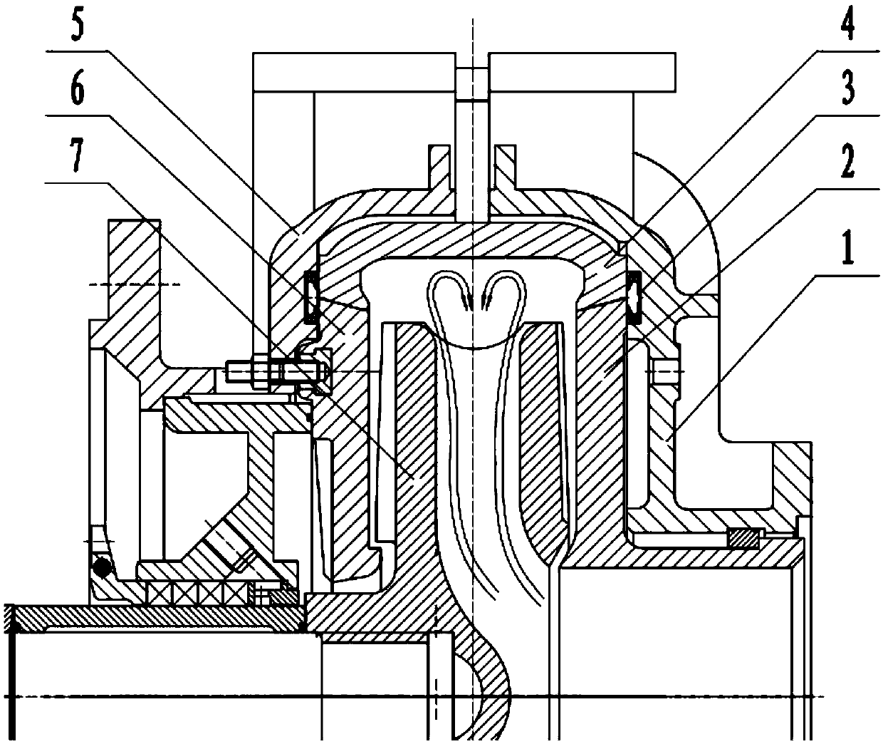
[0013] Such as figure 1 As shown, a vortex impeller in an impurity pump includes a pump cover 1 and a pump body 5, the pump body 5 is located on the top side of the pump cover 1, the pump cover 1 is movably connected with the pump body 5, and the pump body 5 A front cover 2 and a rear cover 6 are movably installed in the inner cavity of the inner cavity, and the front cover 2 and the rear cover 6 are engaged with each other, and the top of the front cover 2 and the rear cover 6 are movably connected with Sheath 4, between sheath 4 and front cover 2 and rear cover 6 is sealed with O-shaped sealing ring 3, the material of said O-shaped sealing ring 3 is rubber material, and said front cover 2 and rear cover An impeller 7 is fixedly installed in t...


PUM


Abstract

The invention provides an impurity in-pump vortex impeller. The impurity in-pump vortex impeller comprises a pump cover and a pump body, wherein the pump body is located at the top side of the pump cover; the pump cover is movably connected with the pump body; a front cover plate and a rear cover plate are movably mounted in an inner cavity of the pump body; the front cover plate and the rear cover plate are clamped with each other; a sheath is movably connected with the tops of the front cover plate and the rear cover plate; an impeller is fixedly mounted in the inner cavity of the front cover plate and the rear cover plate; an outlet of the impeller is designed into a concave shape so that the speed of the front cover plate and the rear cover plate at two sides of the impeller is greaterthan a middle speed; slurry is divided into two paths of fluid at the outlet and is rotated toward the center, so that particles are enforced to flow toward the center and a vortex shape is formed; furthermore, the concentration at two sides is reduced, so that the abrasion to a flow channel of the pump body and two side walls is alleviated and the service life of overflowing parts is prolonged;and the abrasion loss is reduced, the efficiency of a water pump is improved, the shaft power is reduced and the aim of energy saving and environment protection is directly realized.

Description

Technical field: [0001] The invention relates to the technical field of impurity pumps, in particular to an inner vortex impeller of an impurity pump. Background technique: [0002] Generally, the impeller of the impurity pump uses parallel cover plates. After the slurry enters the impeller, an external vortex is formed at the outlet from the center to both sides, which causes serious wear on the front and rear cover plates and inner lining of the impeller, which is the main reason for the short life of the flow-passing parts. reason. Invention content: [0003] The technical problem to be solved by the present invention is to provide a vortex impeller in the impurity pump, so that the flow-passing parts have longer service life, higher efficiency and more stable operation. [0004] In order to achieve the above purpose, the present invention is achieved through the following technical solutions: a vortex impeller in an impurity pump, including a pump cover and a pump bod...

Claims


Application Information

Patent Timeline
Patent Type & Authority Applications(China)
IPC IPC(8): F04D5/00F04D29/18F04D29/66F04D29/08
CPCF04D5/002F04D5/007F04D29/086F04D29/18F04D29/669
Inventor 董小花满敬江高芳红崇超
Owner SANLIAN PUMP IND CO LTD
Why Eureka
Try Eureka