
Lubrication point terminal detection device and lubrication system

A detection device and lubrication system technology, applied in distribution devices, lubricating parts, lubricating oil control valves, etc., can solve the problems of low oil pressure and cannot be detected, and achieve the effects of simple structure, high reliability and wide detection range

Active Publication Date: 2020-09-22
杭州南方中润机械有限公司
View PDF1 Cites 0 Cited by
  • Summary
  • Abstract
  • Description
  • Claims
  • Application Information

AI Technical Summary

Problems solved by technology

[0004] The invention overcomes the disadvantage that the oil pressure on the lubrication pipeline is low and cannot be detected, and provides a lubrication point terminal detection device and a lubrication system. When the oil pressure on the lubrication pipeline is low, the detection device can accurately detect and give feedback in time to the controller, simple structure and high reliability

Method used


Image

  • Lubrication point terminal detection device and lubrication system
  • Lubrication point terminal detection device and lubrication system
  • Lubrication point terminal detection device and lubrication system

Examples


Embodiment 1

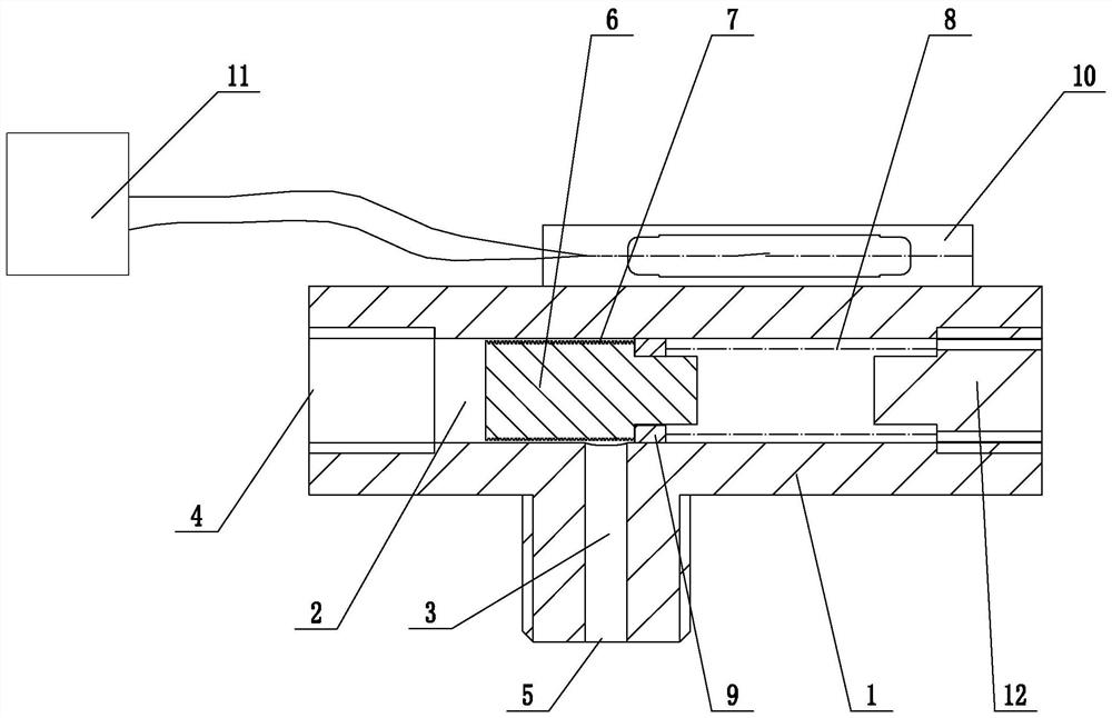
[0023] Embodiment 1: A device for detecting the terminal of a lubrication point (see attached figure 1 ), including the device main body 1 connected to the lubricating point terminal, the device main body is provided with an oil inlet hole 2 and an oil outlet hole 3, one end of the oil outlet hole penetrates to the outer wall of the device main body to form an oil outlet 5, and the other end of the oil outlet hole is connected to the inlet The oil hole is connected, and an axially movable moving part 6 is installed in the corresponding position of the oil inlet hole and the oil outlet hole. The outer wall of the moving part is provided with a spiral oil delivery groove 7, and one end of the oil inlet hole penetrates to the outer wall of the main body of the device to form an oil inlet 4 , an elastic return member 8 is installed between the other end of the oil inlet hole and the moving part, the elastic return member is a return spring, an induction block 9 is installed on the ...

Embodiment 2

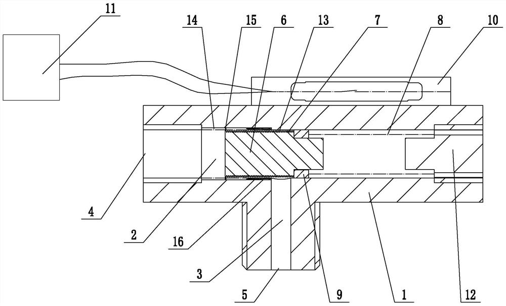
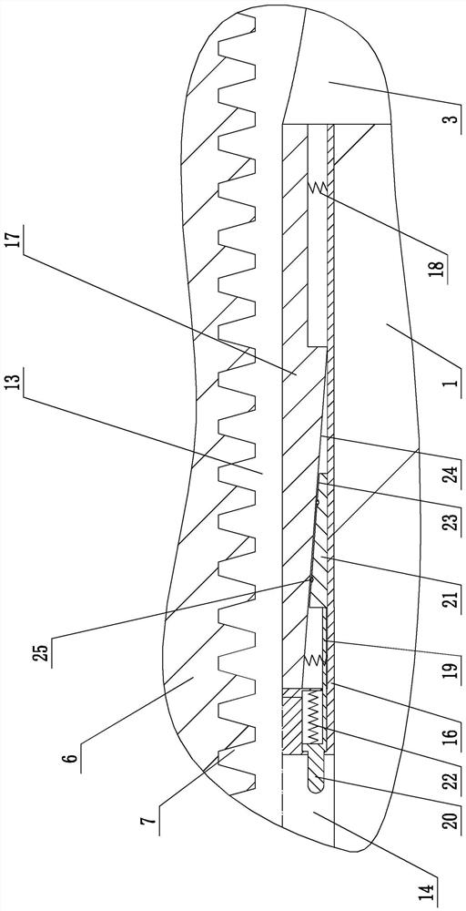
[0026] Embodiment 2: A device for detecting the terminal of a lubrication point (see attached figure 2 , attached image 3 ), its structure is similar to that of Embodiment 1, the main difference is that in this embodiment, there is an oil gap 13 between the outer wall of the moving part and the inner wall of the oil inlet hole, and a number of axially arranged installation grooves are arranged on the inner wall of the oil inlet hole 14. The installation groove extends from the oil inlet to the oil outlet. The end position of the moving part facing the oil inlet and the installation groove are provided with a number of sliding posts 15 one by one. The sliding posts are fitted in the installation groove. A strip-shaped mounting seat 16 is installed in the mounting groove near the end of the oil outlet, and an inserting strip 17 that can move radially toward the moving parts is installed in the mounting seat, and a tension spring 18 is connected between the inserting strip and ...


PUM


Abstract

The invention discloses a lubricating point terminal detection device and a lubricating system, and aims to overcome the shortcomings of XX. The lubricating point terminal detection device comprises adevice main body connected with a lubricating point terminal, and the device main body is provided with an oil inlet and an oil outlet; one end of the oil outlet penetrates through the outer wall ofthe device main body so that an oil discharging port is formed, and the other end of the oil outlet communicates with the oil inlet; a moving component which can be moved axially is arranged at the position, corresponding to the oil outlet, in the oil inlet; the outer wall of the moving component is provided with a spiral oil feeding tank, and one end of the oil outlet penetrates through the outerwall of the device main body so that an oil feeding port is formed; an elastic reset part is installed between the other end of the oil outlet and the moving component, and the moving component is provided with an induction block; the device main body is provided with an induction switch matched with the induction block, and the induction block and the induction switch are arranged in a staggeredmanner; and the induction switch and the elastic reset part are arranged oppositely, and the induction switch is connected with a controller of the lubricating system electrically.

Description

technical field [0001] The invention relates to the technical field of equipment lubrication, more specifically, it relates to a lubrication point terminal detection device and a lubrication system. Background technique [0002] At present, the lubrication system on the market is equipped with a pressure switch (normally open type 0.8-1.2Mpa) in the electric lubrication pump (generally the factory pressure is set at 1.5-1.8Mpa), so that it can only detect the pressure of the main pipeline or cut off the flow , As for the lack of pressure on the sub-pipeline or the disconnection, there will be no detection products, resulting in no detection feedback; when the pressure on the sub-pipeline is missing or cut off, this will cause the lubrication point to not be lubricated in time, and there will be no lubricating oil for a long time, which will cause the friction pair of the equipment to suffer. damage, reducing the accuracy and service life of the equipment. [0003] Chinese p...

Claims


Application Information

Patent Timeline
Patent Type & Authority Patents(China)
IPC IPC(8): F16N7/38F16N23/00F16N25/00F16N29/04
CPCF16N7/38F16N23/00F16N25/00F16N29/04
Inventor 董家龙范轶强
Owner 杭州南方中润机械有限公司
Learn More