Boiler Exhaust Heat Depth Recovery Device

A technology of recycling device and waste heat, applied in the direction of cleaning heat transfer device, indirect heat exchanger, heat exchanger type, etc., can solve the problems of cold water heating, slow response speed, etc. clean and thorough effect

Active Publication Date: 2020-04-28
杭州航民小城热电有限公司
View PDF10 Cites 0 Cited by
  • Summary
  • Abstract
  • Description
  • Claims
  • Application Information

AI Technical Summary

Problems solved by technology

Due to the large amount of water in the casing, when the hot air recovery device operates from a cold state, it takes a long time to heat the cold water, and personnel need to wait for a long time to use the heated water. The boiler heat recovery system exists The defect of slow response

Method used


Image

  • Boiler Exhaust Heat Depth Recovery Device
  • Boiler Exhaust Heat Depth Recovery Device
  • Boiler Exhaust Heat Depth Recovery Device

Examples


Embodiment Construction

[0034] The present invention will be described in further detail below in conjunction with the accompanying drawings.

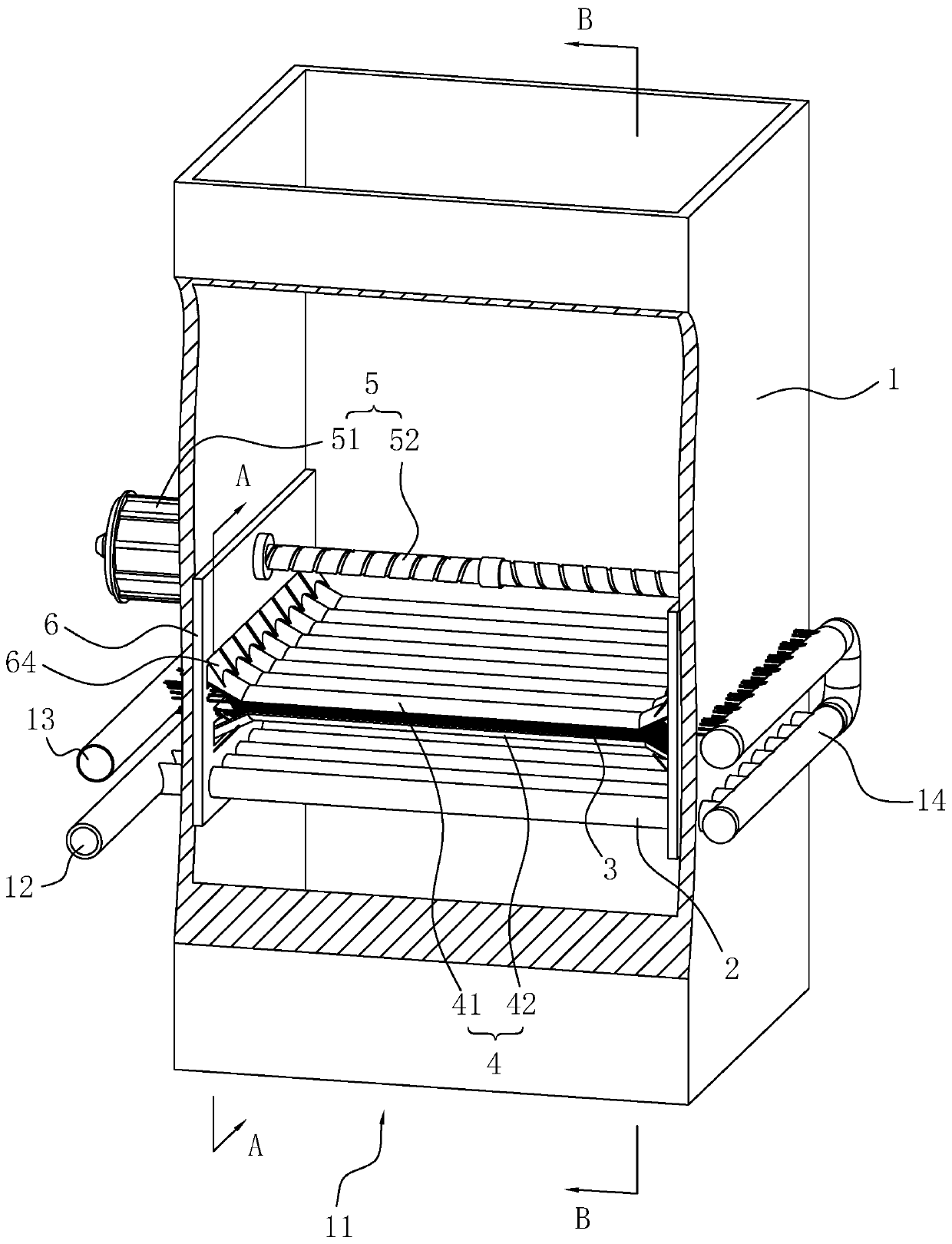
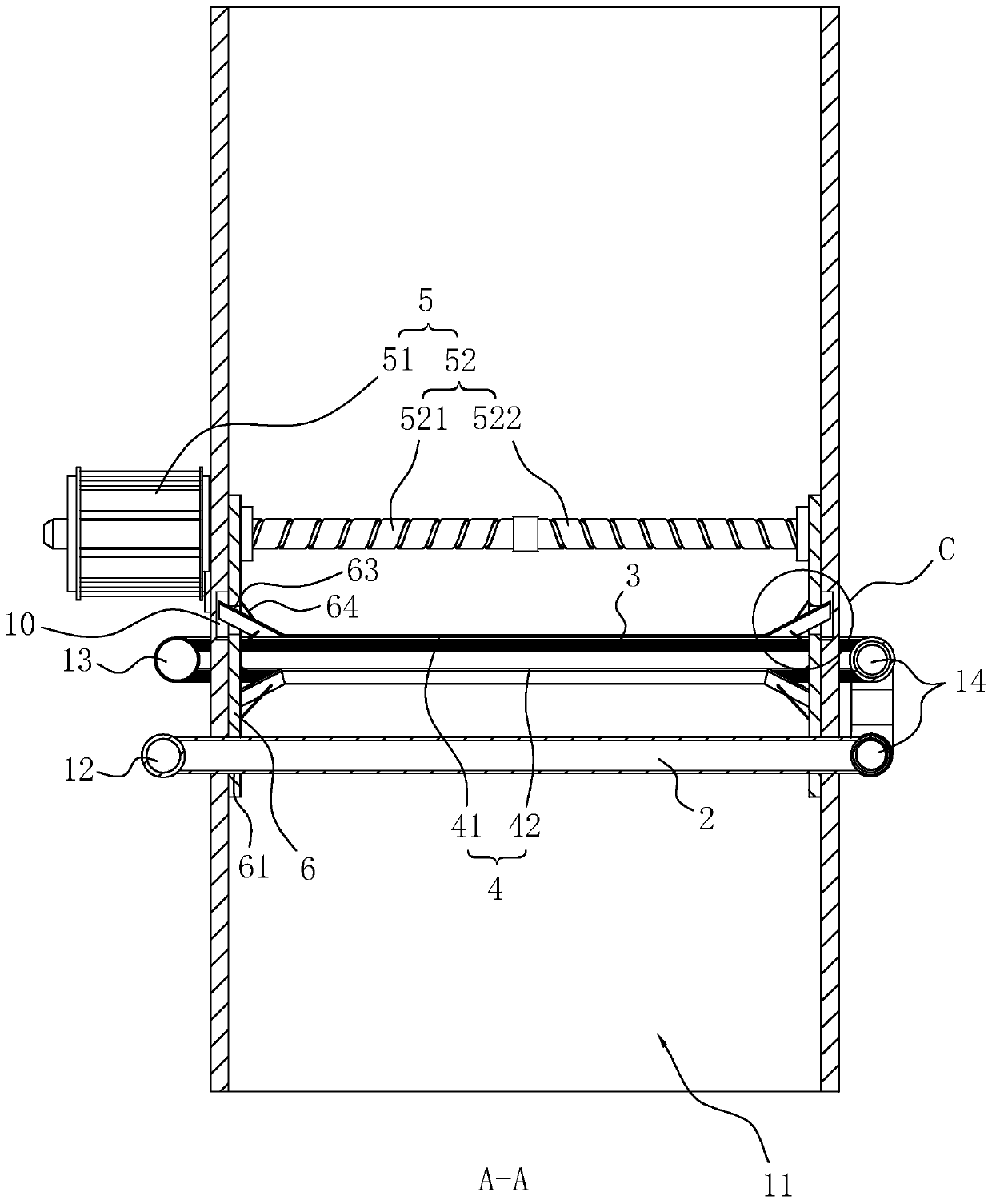
[0035] refer to figure 1 and figure 2 , is a boiler exhaust heat depth recovery device disclosed in the present invention, comprising a cuboid chimney 1, the two ends of the chimney 1 pass through, and one end of the chimney 1 is a smoke inlet 11 for communicating with the boiler flue. A water inlet pipe 12, a water outlet pipe 13, and a connecting pipe 14 are arranged outside the chimney 1, and a plurality of heat pipes 2 and capillary pipes 3 are arranged inside the chimney 1, and each pipeline is arranged according to the water inlet pipe 12, the heat pipe 2, the connecting pipe 14, the capillary pipe 3, and the water outlet pipe. The sequence of 13 is connected successively, and each pipeline is a metal pipe.

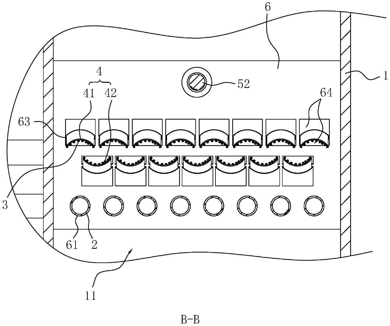
[0036] All the heat pipes 2 are located on the same cross-section of the chimney 1, and all the heat pipes 2 are parallel to each other and eve...


PUM


Abstract

The invention discloses a boiler exhaust smoke waste heat deep recovery device and relates to the technical field of waste heat recovery. The key of the technical scheme is that the boiler exhaust smoke waste heat deep recovery device comprises a chimney, the chimney comprises a smoke inlet communicating with a boiler flue, multiple heat pipes and capillary pipes are arranged in the chimney in a penetrating manner and are made of metal, the two ends of each heat pipe and the two ends of each capillary pipe are connected with the side walls of the chimney correspondingly, and the heat pipes arelocated between the capillary pipes and the smoke inlet; a water inlet pipe and a water outlet pipe are arranged outside the chimney, all the heat pipes communicate with the water inlet pipe, and thecapillary pipes communicate with the water outlet pipe; a communicating pipe is further arranged outside the chimney, the communicating pipe enables the ends, far away from the water inlet pipe, of the heat pipes and the ends, far away from the water outlet pipe, of the capillary pipes to communicate. The boiler exhaust smoke waste heat deep recovery device has the advantages of quick heat recovery response and rapid water temperature rising; through arrangement of ash removing plates and a driving mechanism, ash removal can be conducted on all pipelines to ensure the thermal conductivity, heat collecting plates can be separated from the capillary pipes, and clean and thorough ash removal can be conducted on the capillary pipes and the heat collector plates.

Description

technical field [0001] The invention relates to the technical field of waste heat recovery, in particular to a deep recovery device for waste heat of boiler exhaust smoke. Background technique [0002] At present, various boilers such as steam boilers, heating boilers, drinking water boilers, etc. adopt various energy-saving devices, but the flue gas emitted by the chimney still has a large amount of heat, and the heat of the flue gas is discharged into the air, resulting in energy waste. phenomenon; therefore, there have been devices capable of recovering and utilizing boiler exhaust heat in the prior art. [0003] The Chinese utility model patent with the existing authorized announcement number CN203534282U discloses a boiler heat recovery system, including a burner, a boiler, a hot air recovery device and a hot water tank. The burner is used to heat the boiler; the hot exhaust gas generated by the burner The heat in the tank is recovered by the hot air recovery device; t...

Claims


Application Information

Patent Timeline
Patent Type & Authority Patents(China)
IPC IPC(8): F23J15/06F28D1/053F28G1/08F28G15/04
CPCF23J15/06F28D1/05341F28G1/08F28G15/04Y02E20/30
Inventor 沈利翔孙元龙
Owner 杭州航民小城热电有限公司
Why Eureka
Try Eureka