Unlock instant, AI-driven research and patent intelligence for your innovation.

Thickness flatness level difference detection device, system and method

A detection device and flatness technology, applied in the field of thickness flatness level difference detection devices, can solve the problems of low precision and slow detection speed, and achieve the effects of high precision and good stability

Active Publication Date: 2021-02-26
深圳佳视德智能科技有限公司
View PDF9 Cites 0 Cited by
  • Summary
  • Abstract
  • Description
  • Claims
  • Application Information

AI Technical Summary

Problems solved by technology

The detection speed is slow and the accuracy is low, and it is only used for the detection of flatness

Method used


Image

  • Thickness flatness level difference detection device, system and method
  • Thickness flatness level difference detection device, system and method
  • Thickness flatness level difference detection device, system and method

Examples


Embodiment

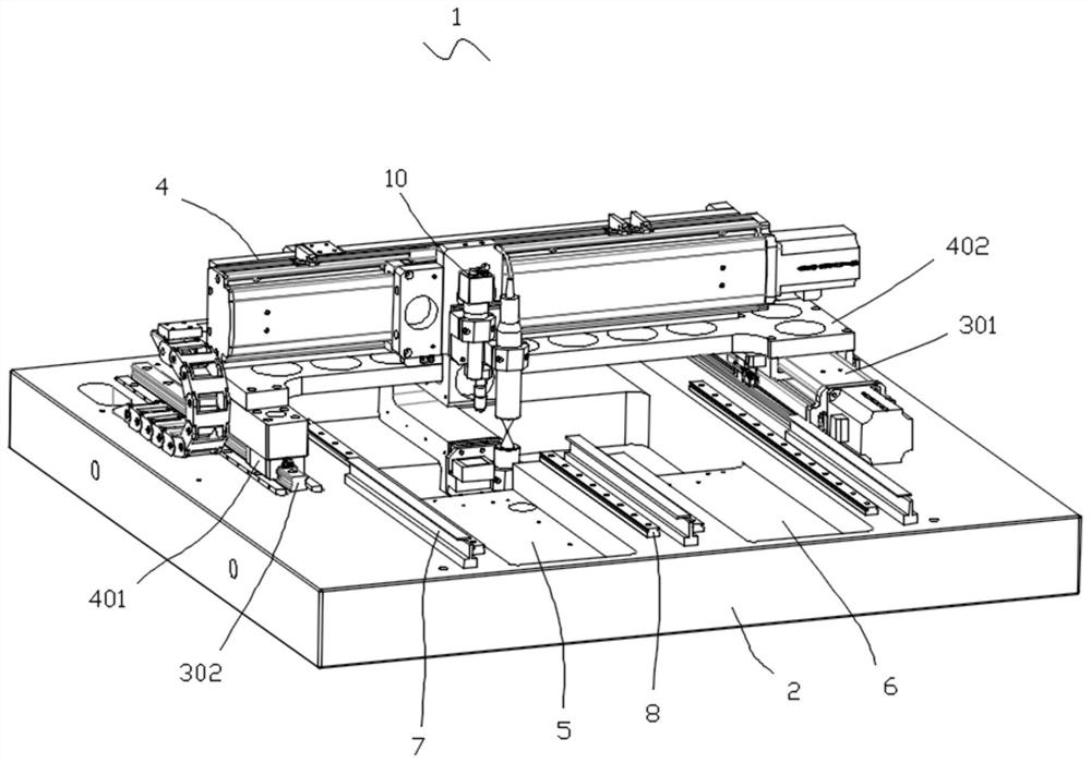
[0042] Such as figure 1As shown, this embodiment provides a thickness flatness level difference detection device 1, which is suitable for the appearance detection of the detected object, especially the thickness, flatness and level difference detection. Specifically, the thickness flatness level difference detection device 1 includes a workbench 2 , a double-layer moving platform and a detection component 10 .

[0043] Wherein, the workbench 2 is used for installing the double-layer mobile platform, the detection component 10 and the detected object. Exemplarily, as figure 1 As shown, the top of the workbench 2 is a square platform, and the workbench 2 is provided with a groove or a larger-sized through hole 11 to accommodate part of the structure in the detection assembly 10, so that the overall structure of the thickness flatness level difference detection device 1 More compact and smaller.

[0044] Preferably, there are multiple detection stations on the workbench 2, and...


PUM


Abstract

The invention provides a detection device, system and method for thickness flatness step difference, the device includes: a workbench; a double-layer mobile platform, the double-layer mobile platform includes a first-level mobile platform and a second-level mobile platform; a detection component, the detection component includes The mounting frame, the first spectral confocal detection device, and the second spectral confocal detection device, the mounting frame is installed on the second-level mobile platform, and the first spectral confocal detection device and the second spectral confocal detection device are on the mounting frame. The up and down installation is opposite, so that the detected object is located in the gap between the first spectral confocal detection device and the second spectral confocal detection device. Compared with the existing technology, it not only has high precision, but also is easy to introduce storage and analysis modules to realize intelligent detection. It can realize accurate point, line and surface scanning of any material product, and obtain the thickness, flatness and step difference of the product.

Description

technical field [0001] The invention relates to the field of detection equipment, in particular to a detection device, system and method for thickness flatness step difference. Background technique [0002] The traditional flatness tester is an instrument designed according to the principle of optical self-collimation. It can measure the straightness error of the machine tool or the guide rail of the instrument, and can also measure the flatness error of the flat plate. and other accessories. However, the traditional flatness tester requires manual observation, such as rising labor costs, heavy operator workload, low efficiency, unstable detection accuracy, etc., and the detection data cannot be automatically recorded, and the degree of intelligence is low. [0003] With the development of technology, some digital detectors have appeared. In the prior art, such devices can only detect flatness alone, and are dedicated machines. The detection speed is slow and the precisio...

Claims


Application Information

Patent Timeline
Patent Type & Authority Patents(China)
IPC IPC(8): G01B11/02G01B11/06G01B11/30
CPCG01B11/02G01B11/022G01B11/06G01B11/30
Inventor 陈业吴落得贺平李均华黄细刚
Owner 深圳佳视德智能科技有限公司