
Ion implantation machine and working method thereof

An ion implanter and ion beam technology, applied in the field of ion implanters, can solve the problems of high downtime frequency of ion implanters, achieve the effect of reducing downtime frequency and improving consistency

Inactive Publication Date: 2019-04-26
HUAIAN IMAGING DEVICE MFGR CORP
View PDF4 Cites 0 Cited by
  • Summary
  • Abstract
  • Description
  • Claims
  • Application Information

AI Technical Summary

Problems solved by technology

[0003] However, the downtime frequency of existing ion implanters is high

Method used


Image

  • Ion implantation machine and working method thereof
  • Ion implantation machine and working method thereof
  • Ion implantation machine and working method thereof

Examples


Embodiment Construction

[0022] As mentioned in the background, the downtime frequency of ion implanters is relatively high.

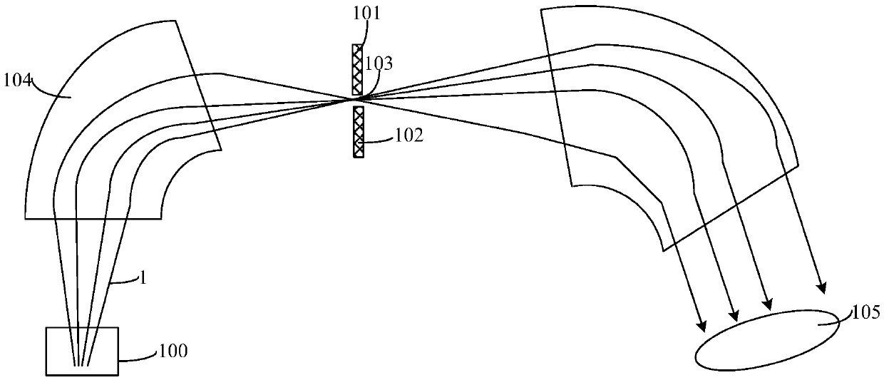
[0023] figure 1 It is a schematic diagram of the structure of an ion implanter.

[0024] Please refer to figure 1 , the ion implanter includes: an ion source 100 for emitting an ion beam 1; a base 105 for holding a wafer; a first baffle plate 101 and a first barrier between the ion source 100 and the base 105 separated from each other. Two baffles 102 , an opening 103 is formed between the first baffle 101 and the second baffle 102 , and the opening 103 is used for passing the ion beam 1 .

[0025] In the above ion implanter, there is a first deflection device 104 between the first baffle 101 and the ion source 100 , and the first deflection device 104 is used to screen the ion beam 1 . After the ion beam 1 is screened by the first deflection device 104, the width of the ion beam 1 is greater than the size of the opening 103, so that part of the ion beam 1 is blocked by the...


PUM

PropertyMeasurementUnit
Angleaaaaaaaaaa
Angleaaaaaaaaaa

Abstract

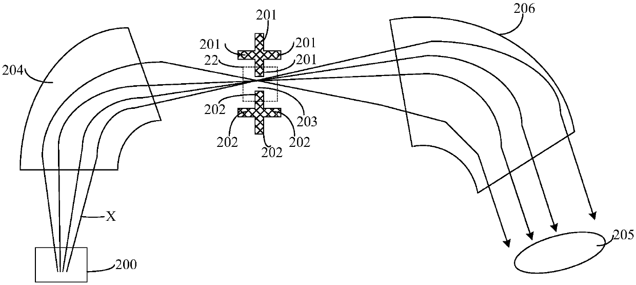
The invention provides an ion implantation machine and a working method thereof. The ion implantation machine comprises an ion source, a base, a first baffle structure, a second baffle structure and aswitcher, wherein the ion source is used for emitting ion beams; the base is used for containing wafers; the first baffle structure and the second baffle structure are located between the ion sourceand the base, the first baffle structure is separated from the second baffle structure, the first baffle structure comprises a plurality of first baffles, and the second baffle structure comprises a plurality of second baffles; the switcher makes one first baffle and one second baffle in a working surface, an opening structure is formed between the first baffle and second baffle in the working surface, and the opening structure enables the ion beams to pass. The ion implantation machine is utilized to improve the consistency of ion implantation of different batches of the wafers and also reduce the downtime frequency.

Description

technical field [0001] The invention relates to the field of semiconductors, in particular to an ion implanter and a working method thereof. Background technique [0002] Ion implantation is widely used in semiconductor manufacturing technology. It is a method to introduce a controllable amount of impurities into semiconductor materials to change their electrical properties. The most important use is to dope semiconductor materials. The ion implantation process is carried out in an ion implanter. The ion beam (Ion Beam) incident by the ion source scans the entire wafer (Wafer), so that the semiconductor material on the wafer surface is evenly doped. [0003] However, the downtime frequency of existing ion implanters is relatively high. Contents of the invention [0004] The technical problem solved by the present invention is to provide an ion implanter and its working method, so as to reduce the downtime frequency of the ion implanter. [0005] In order to solve the abo...

Claims


Application Information

Patent Timeline
IPC IPC(8): H01J37/32H01L21/67
CPCH01J37/32H01J37/32431H01L21/67011
Inventor 邸太平洪纪伦吴宗祐林宗贤
Owner HUAIAN IMAGING DEVICE MFGR CORP
Learn More