Mixing valve

A technology for mixing valves and mixtures, which is applied in the direction of mixers, fluid mixers, multi-way valves, etc., can solve the problems of flushing loss, system change, large dead zone, etc., and achieve the effect of simple nozzle replacement and easy maintenance

Active Publication Date: 2019-04-26
DUERR SYST GMBH
View PDF6 Cites 2 Cited by
  • Summary
  • Abstract
  • Description
  • Claims
  • Application Information

AI Technical Summary

Problems solved by technology

[0004] A disadvantage of known valve arrangements for mixing different coating agent components (e.g. masterbatches and hardeners) is the relatively large dead space in the mixing chamber, which leads to considerable flushing losses when the system is at a standstill
[0005] In addition, known valve arrangements run the risk of drying out, which in the worst case leads to a complete loss of function due to curing
[0006] In addition, the nozzle and feed unit are difficult to clean
[0007] In addition, the mixing ratio of various coating agent components can usually only be changed by replacing the corresponding mixing head, so if the mixing ratio is changed, the system must also be changed
[0008] Finally, the known valve arrangement also requires an additional shut-off valve

Method used


Image

  • Mixing valve
  • Mixing valve
  • Mixing valve

Examples


Embodiment Construction

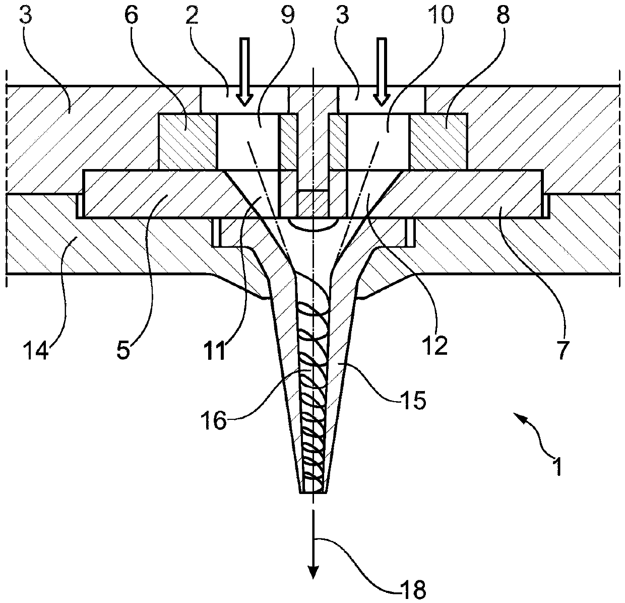
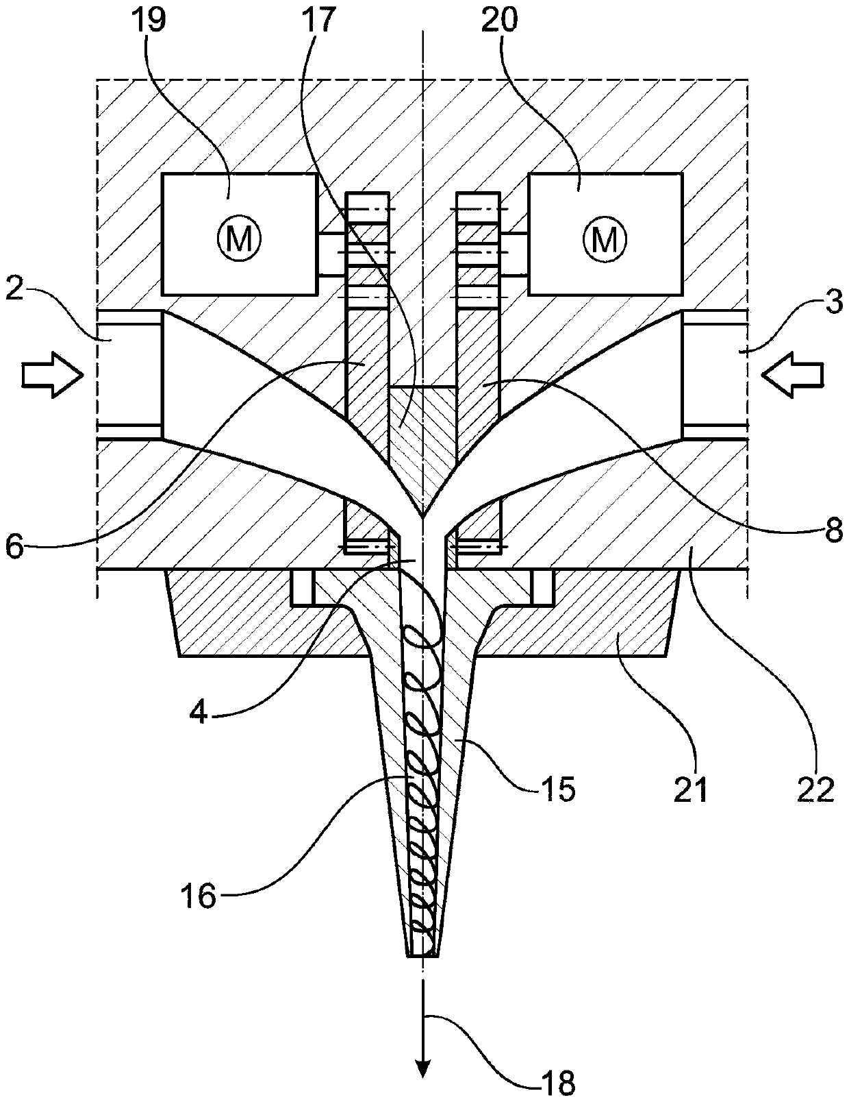
[0050] Figure 1A and 1B Different views are shown of an initial example of a mixing valve 1 of the invention, which can be used, for example, in a paint shop for painting body components in order to mix different coating agent components of thick materials.

[0051] The mixing valve 1 has two coating agent inlets 2 , 3 through which the two coating agent components are fed separately from one another.

[0052] Furthermore, the mixing valve 1 has a coating agent outlet 4 , through which the multicomponent mixture of the two aforementioned coating agents exits.

[0053] Between the two coating agent inlets 2 , 3 and the coating agent outlet 4 there are two coating agent valves which control the flow of coating agent through the coating agent inlet 2 or 3 .

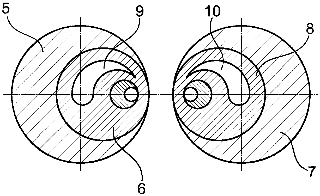
[0054] The coating agent valve between the coating agent inlet 2 and the coating agent outlet 4 has a fixed valve disk 5 and a rotatable valve disk 6 .

[0055] A further coating agent valve between coating agent inlet 3 an...


PUM


Abstract

The invention relates to a mixing valve (1) for mixing two coating agent components (e.g. a base and a hardener) to form a multi-component mixture, comprising two coating agent inlets (2) for supplying the two coating agent components, two coating agent valves (5-8) for controlling the coating agent flow through the two coating agent inlets (2, 3), as well as a coating agent outlet (4) for the delivery of the multi-component mixture in a specified outflow direction (18). The invention provides that at least one of the coating agent valves (5-8) is designed as a rotary slide valve having two plane-parallel valve disks (5-8) which are rotatable relative to each other about a rotational axis.

Description

technical field [0001] The invention relates to a mixing valve for mixing two coating agent components into a multicomponent mixture, in particular for mixing adhesive components of multicomponent adhesives or for mixing Components of sealing materials. Background technique [0002] In modern painting systems for painting body components, coating agents are often used which are mixed together from several components. An example of such a multicomponent mixture is, for example, an adhesive or thickener for sound insulation or sealing. Another example is so-called two-component coatings consisting of a masterbatch and a hardener. [0003] In this multi-component system, the various coating agents are brought together through the coating agent valve and then mixed. There are various problems in the prior art, which are briefly described below. [0004] A disadvantage of known valve arrangements for mixing different coating agent components, such as masterbatch and hardener,...

Claims


Application Information

Patent Timeline
Patent Type & Authority Applications(China)
IPC IPC(8): B05B7/04B05B12/14B05C11/10F16K11/074B05B7/12B05B1/34B05B1/30
CPCB05B1/3026B05B1/3405B05B7/0408B05B7/1209B05B12/1418B05C11/1036F16K11/074B05C5/0233F16K3/085B01F25/1051B01F35/833
Inventor F·施努尔
Owner DUERR SYST GMBH
Why Eureka
Try Eureka