Method for regulating an internal combustion engine for supercharging

An adjustment method and internal combustion engine technology, applied to internal combustion piston engines, combustion engines, mechanical equipment, etc., can solve problems such as efficiency needs to be improved, compressor surge, etc.

Active Publication Date: 2022-03-08
ROLLS ROYCE SOLUTIONS GMBH
View PDF8 Cites 0 Cited by
  • Summary
  • Abstract
  • Description
  • Claims
  • Application Information

AI Technical Summary

Problems solved by technology

While the method described solves the problem of compressor surge after accelerator pedal release, it leaves room for improvement, for example in terms of efficiency

Method used


Image

  • Method for regulating an internal combustion engine for supercharging
  • Method for regulating an internal combustion engine for supercharging
  • Method for regulating an internal combustion engine for supercharging

Examples


Embodiment Construction

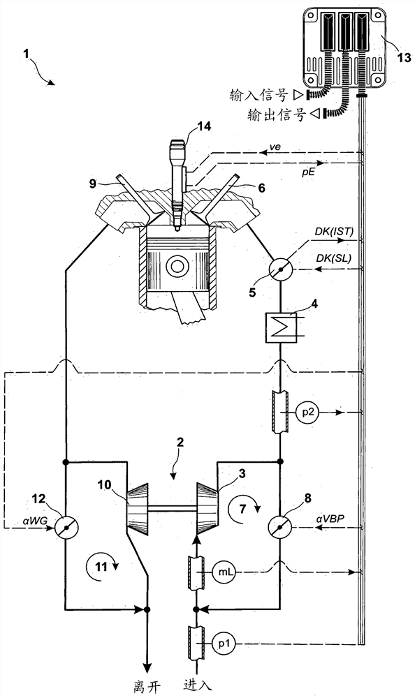
[0015] figure 1 A simplified system diagram of an internal combustion engine 1 with an exhaust gas turbocharger 2 is shown. The exhaust gas turbocharger 2 includes a compressor 3 and a turbine 10 . The further design and function of exhaust gas turbocharger 2 are assumed to be known. The air path for supplying combustion air comprises a compressor 3 , a charge air cooler 4 , a throttle valve 5 and an intake valve 6 in the cylinder head of the internal combustion engine 1 . The air path is supplemented by a compressor bypass 7 with a compressor bypass valve 8 . Charge air is conducted from the secondary side of the compressor 3 back to the primary side of the compressor 3 via the compressor bypass 7 . The exhaust path includes exhaust valves 9 in the cylinder heads of the internal combustion engine 1 and the turbine 10 . The exhaust gas path is supplemented by a turbine bypass 11 with a turbine bypass valve 12 .

[0016] Internal combustion engine 1 is controlled and regul...


PUM


Abstract

A control method for a supercharged internal combustion engine (1) is proposed, in which the operating point of the compressor is adjusted in the characteristic field of the compressor by means of the compressor-position controller (16) as a function of the throttle-control deviation (dDK), This is achieved by calculating both the first manipulated variable (αVBP) for actuating the compressor-bypass valve and the second one for actuating the turbine-bypass valve via the compressor-position regulator ( 16 ). Two control variables (αWG), and wherein the operating point of the compressor is corrected via the correction regulator ( 22 ) as a function of the air mass-control deviation (dmL) in that the correction regulator ( 22 ) not only calculates the Based on the first correction variable (KORR1) for correcting the first controlled variable (αVBP), a second correction variable (KORR2) for correcting the second controlled variable (αWG) is calculated.

Description

technical field [0001] The invention relates to a control method for a supercharged internal combustion engine, in which an operating point is determined in a compressor characteristic field by setting a compressor bypass valve and a turbine bypass valve. Background technique [0002] A method for a single-stage supercharged internal combustion engine having a compressor bypass valve and a turbine bypass valve is known from DE 10 2014 215 180 A1. The method is based on a typical compressor characteristic field, which describes the distribution of air mass flow and charge pressure. An impermissible operating range for stronger compressor surges and a range for weaker compressor surges are shown within the compressor characteristic field. The method now consists in ascertaining the position of the operating point in the compressor characteristic field after throttle release and actuating the compressor bypass valve and the turbine bypass valve accordingly. If, for example, i...

Claims


Application Information

Patent Timeline
Patent Type & Authority Patents(China)
IPC IPC(8): F02D41/00F02B37/16F02B37/18F02D41/18
CPCF02D41/18F02B37/16F02B37/18F02D41/0007F02D2200/0404F02D2200/0406Y02T10/12F02D33/02
Inventor A.弗洛尔C.基贝勒
Owner ROLLS ROYCE SOLUTIONS GMBH
Why Eureka
Try Eureka