Evaporated fuel treatment device
A technology for evaporating fuel and processing device, which is applied in the field of evaporating fuel processing device and can solve problems such as pressure drop in a fuel tank
- Summary
- Abstract
- Description
- Claims
- Application Information
AI Technical Summary
Problems solved by technology
Method used
Image

Examples
no. 1 example
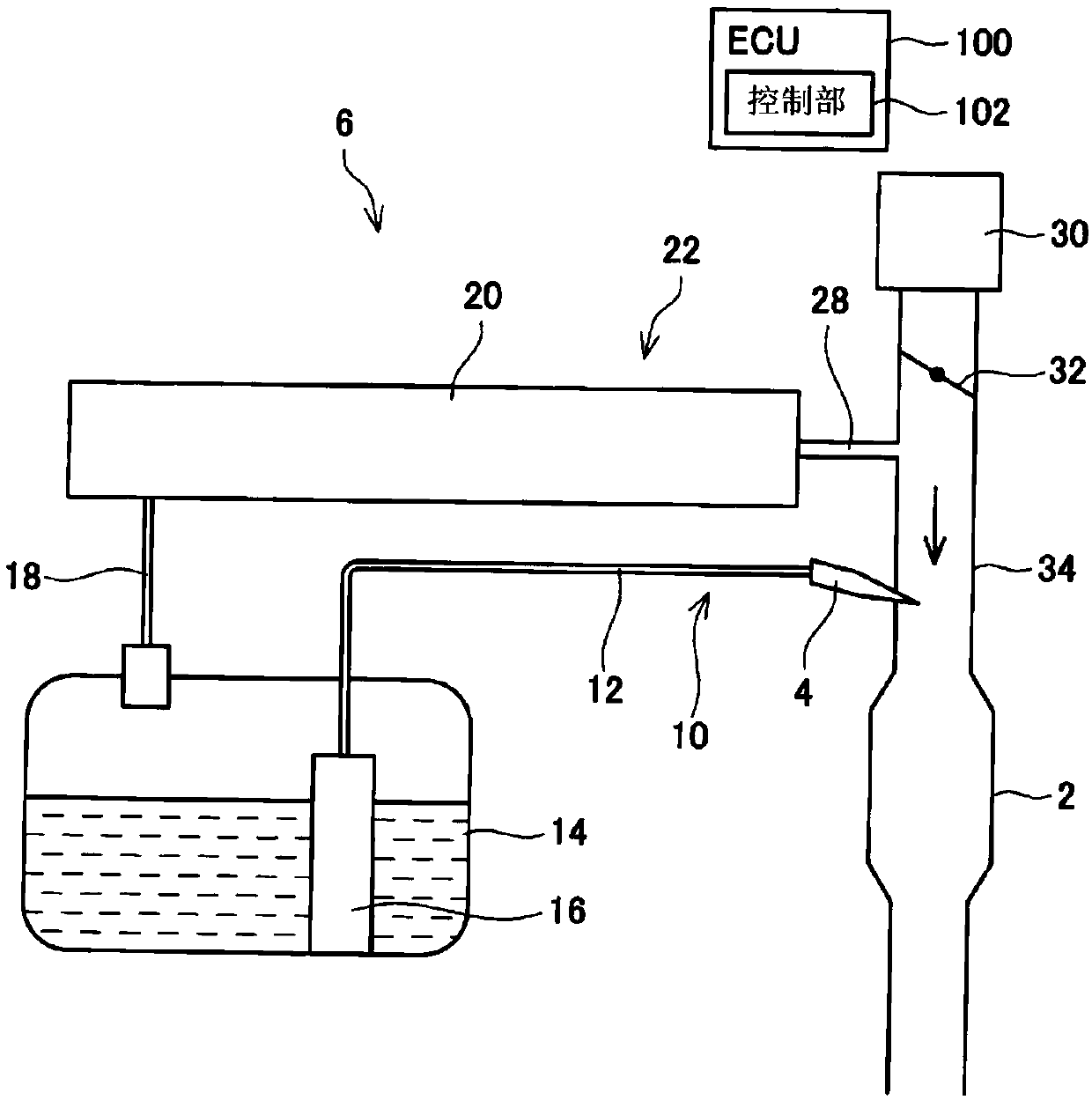
[0050] refer to figure 1 The fuel supply system 6 including the evaporated fuel processing device 20 will be described. The fuel supply system 6 includes: a main supply path 10 for supplying the fuel stored in the fuel tank 14 to the engine 2 ; and a purge supply path 22 for supplying evaporated fuel generated in the fuel tank 14 to the engine 2 .
[0051] A fuel pump member 16 , a supply path 12 , and an injector 4 are provided on the main supply path 10 . The fuel pump unit 16 includes a fuel pump, a pressure regulator, a control circuit, and the like. The fuel pump unit 16 controls the fuel pump according to a signal supplied from the ECU 100 . The fuel pump boosts the fuel in the fuel tank 14 and discharges it. The fuel injected from the fuel pump is pressure-regulated by a pressure regulator, and is supplied from the fuel pump unit 16 to the supply path 12 . The supply path 12 is connected to a fuel pump unit 16 and the injector 4 . The fuel supplied to the supply ...
no. 2 example
[0093] Points different from the first embodiment will be described. Such as Figure 9 As shown, compared with the evaporated fuel processing device 20 of the first embodiment, the evaporated fuel processing device 20 of the second embodiment includes a pump 248 instead of the pump 48 . The pump 248 is controlled by the control unit 102 and pressure-feeds gas from the side of the canister 19 to the side of the air filter (that is, the side of the atmosphere) through the atmosphere path 17 .
[0094] The control unit 102 executes a process of detecting whether the first to third pressure sensors 42 , 44 , 46 and the pump 48 are not operating normally. This processing includes Figure 10 shown in the stress detection process and Figure 12 to Figure 15 The normal judgment processing shown.
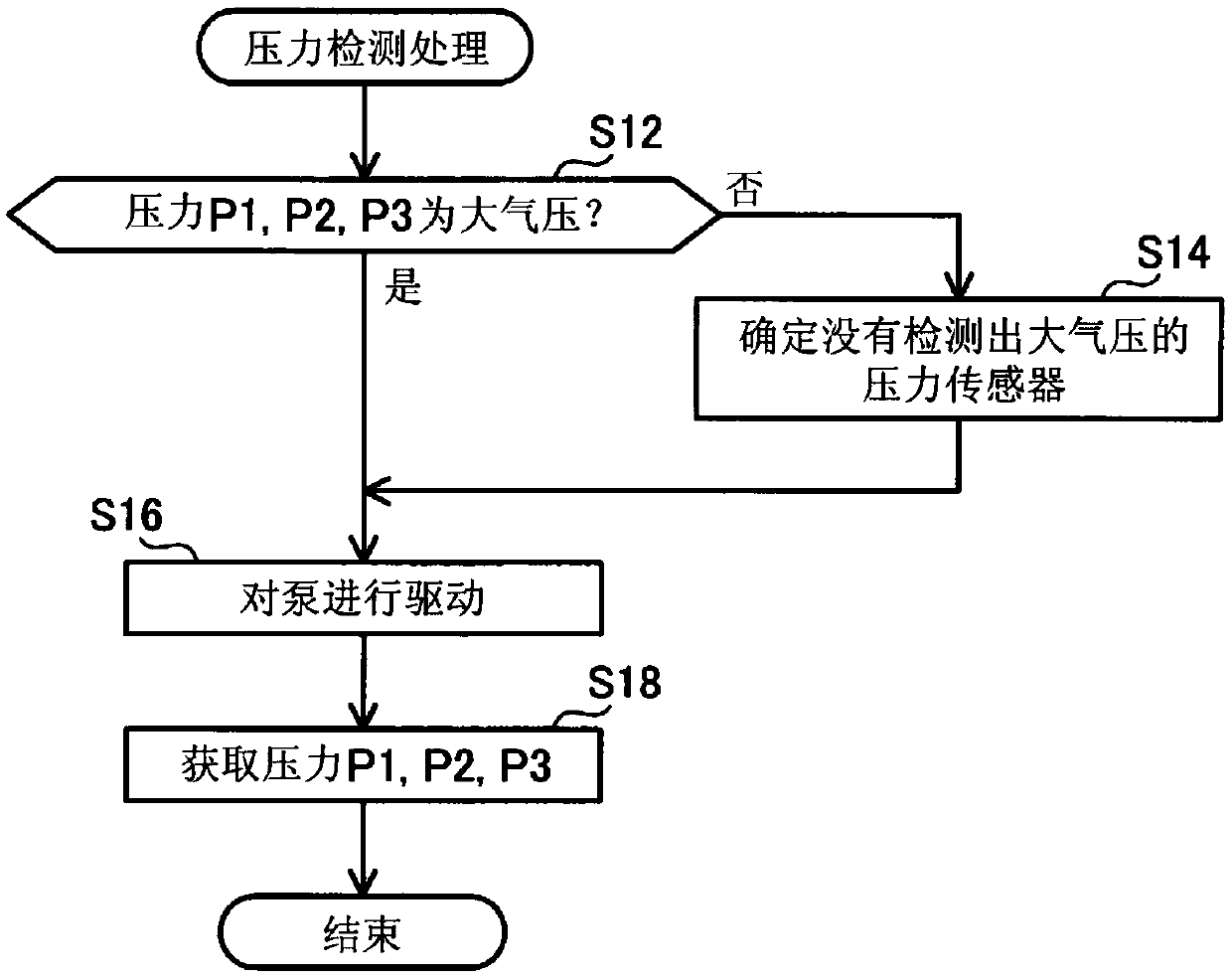
[0095] In stress detection processing, with image 3 The processing of S72 to S76 is similarly performed in S12 to S16. In S76 , the communication space 15 is brought into a negative p...
no. 3 example
[0117] Points different from the first embodiment will be described. Such as Figure 16 As shown, compared with the evaporated fuel processing device 20 of the first embodiment, the evaporated fuel processing device 20 of the third embodiment includes a pump 348 instead of the pump 48 . Pump 348 is disposed on purge path 24 . The pump 348 is arranged between the first pressure sensor 42 and the adsorption tank 19 . The pump 348 is controlled by the control unit 102 to pressure-feed gas from the side of the adsorption tank 19 to the side of the control valve 26 .
[0118] The evaporated fuel processing device 20 further includes an atmospheric valve 347 . The atmospheric valve 347 is arranged on the atmospheric path 17 . The atmospheric valve 347 is arranged on the atmospheric side of the second pressure sensor 44 . The atmospheric valve 347 is switched between opening and closing by the controller 102 . When the valve is opened, it is in an atmosphere communication state...
PUM
 Abstract
Description
Claims
Application Information
 - R&D
- Intellectual Property
- Life Sciences
- Materials
- Tech Scout
- Unparalleled Data Quality
- Higher Quality Content
- 60% Fewer Hallucinations
Browse by: Latest US Patents, China's latest patents, Technical Efficacy Thesaurus, Application Domain, Technology Topic, Popular Technical Reports.
© 2025 PatSnap. All rights reserved.Legal|Privacy policy|Modern Slavery Act Transparency Statement|Sitemap|About US| Contact US: help@patsnap.com