Fuel cell system with load management

a technology of load management and fuel cell, applied in the direction of battery/fuel cell control arrangement, electrochemical generator, electric device, etc., can solve the problems of some limitations, and achieve the effect of partial redundancy

Inactive Publication Date: 2008-06-24
DCNS SA
View PDF81 Cites 37 Cited by
  • Summary
  • Abstract
  • Description
  • Claims
  • Application Information

AI Technical Summary

Problems solved by technology

Because fuel cell system 10 relies upon a single fuel cell stack and a single fuel processor, it suffers from some limitations due to its reliance on those components.

Method used


Image

  • Fuel cell system with load management
  • Fuel cell system with load management
  • Fuel cell system with load management

Examples


Embodiment Construction

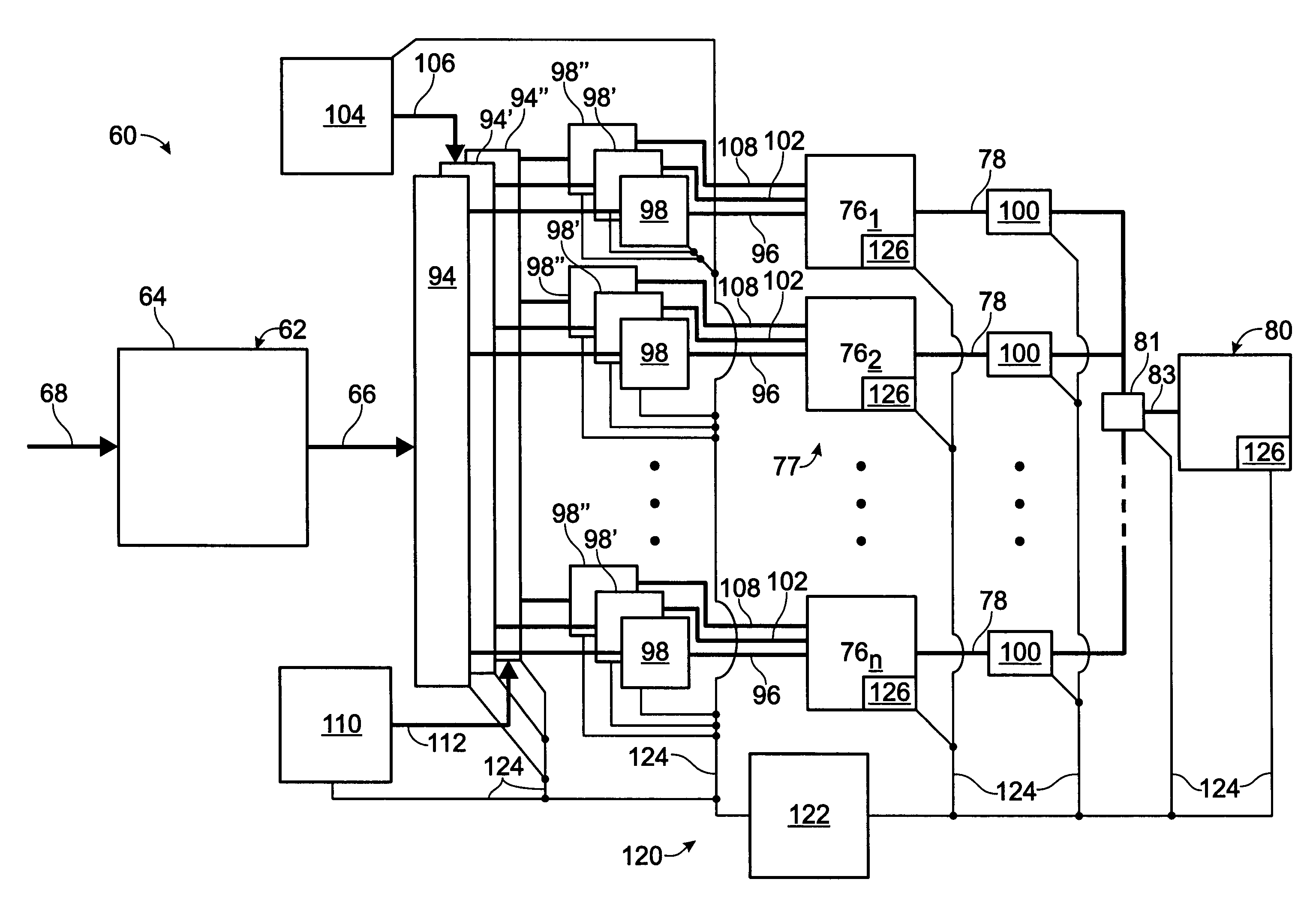
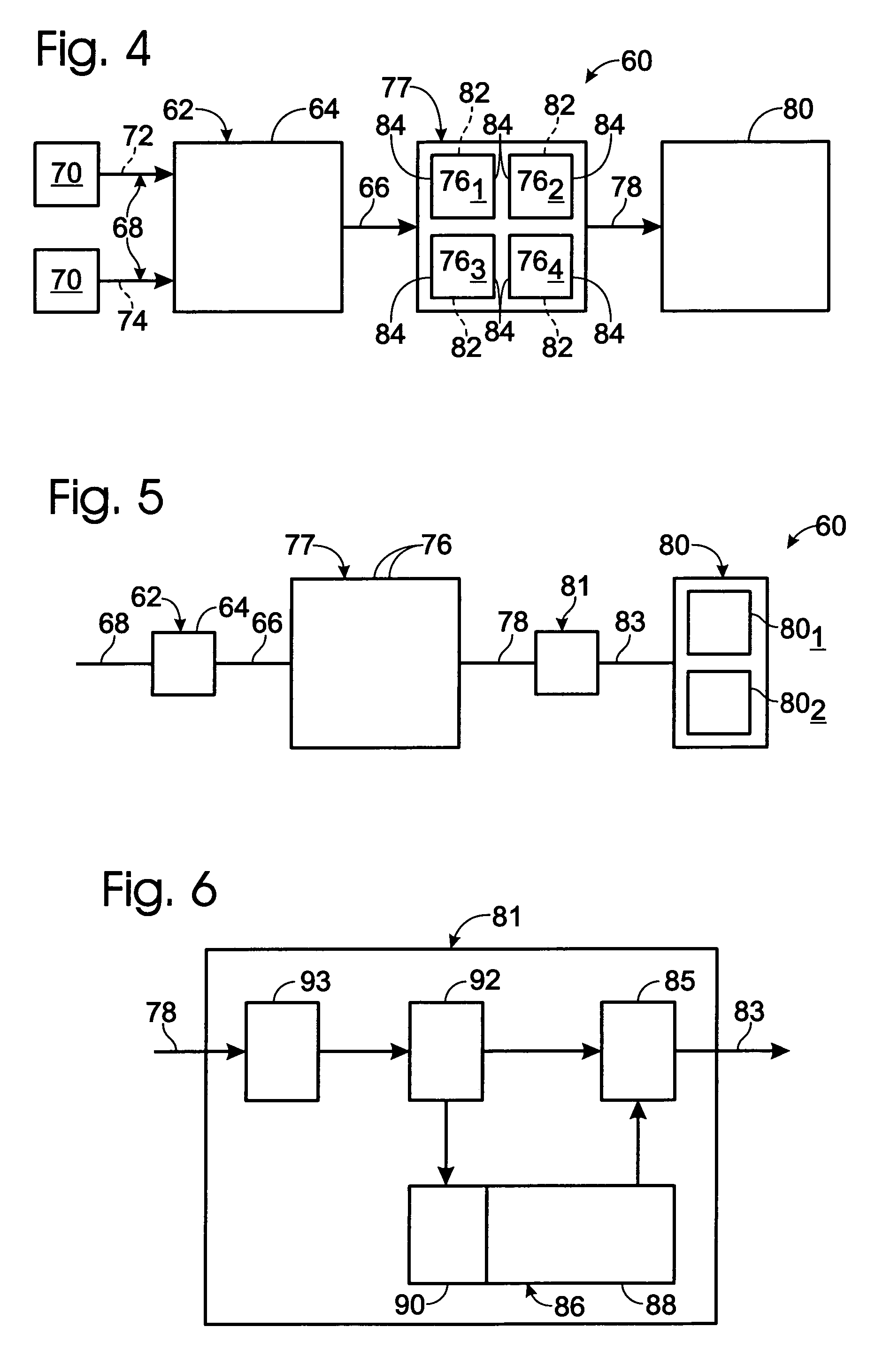
[0028]A fuel cell system constructed according to the present invention is shown in FIG. 4 and generally indicated at 60. System 60 includes a fuel processing assembly 62, which includes a fuel processor 64 that is adapted to produce a product hydrogen stream 66 from a feedstock delivered via feed stream 68. It should also be understood that the components of system 60 have been schematically illustrated and that the fuel cell system may include additional components other than those specifically illustrated in the figures, such as feed pumps, air delivery systems, heat exchangers, heating assemblies and the like, such as disclosed in the incorporated references.

[0029]Fuel processor 64 may produce product hydrogen stream 66 via any suitable mechanism. Examples of suitable mechanisms include steam reforming and autothermal reforming, in which reforming catalysts are used to produce hydrogen gas from a feed stream containing a carbon-containing feedstock and water. Other suitable mech...


PUM

PropertyMeasurementUnit
poweraaaaaaaaaa
rated poweraaaaaaaaaa

Abstract

A fuel cell system having partial and / or total redundancy of at least one operational component, such as a redundancy of fuel cell stacks and / or fuel processors. In some embodiments, the fuel cell system includes a plurality of fuel cell stacks adapted to deliver the same maximum rated power output as a comparative fuel cell system having only a single fuel cell stack. In some embodiments, the fuel cell system includes a plurality of fuel cell stacks adapted to deliver more than the maximum rated power output of the comparative fuel cell system. In some embodiments, the fuel cell system includes a plurality of fuel cell stacks having at least n+1 (or total) redundancy compared to a fuel cell system having only a single fuel cell stack. In some embodiments, the fuel cell system includes a control system and / or structure adapted to limit the applied load to the system.

Description

RELATED APPLICATIONS[0001]This application is a divisional patent application of and claims priority to U.S. patent application Ser. No. 09 / 815,180, which was filed on Mar. 22, 2001, issued on Dec. 28, 2004 as U.S. Pat. No. 6,835,481, and which claims priority to U.S. Provisional Patent Application Ser. No. 60 / 193,052, which was filed on Mar. 29, 2000, and is entitled “Fuel Cell System.” The complete disclosures of the above-identified patent application are hereby incorporated by reference for all purposes.FIELD OF THE INVENTION[0002]The present invention relates generally to energy-production systems, and more particularly to fuel cell systems that include a plurality of fuel cell stacks.BACKGROUND OF THE INVENTION[0003]Fuel cell systems include a fuel processor and a fuel cell stack. The fuel cell stack produces an electric current from the product stream of the fuel processor. For example, the fuel processor may produce hydrogen gas or hydrogen-rich gas from common feed stocks, ...

Claims


Application Information

Patent Timeline
Patent Type & Authority Patents(United States)
IPC IPC(8): H01M8/10H01M8/04H01M8/12H01M8/18H01M8/00B60L3/00B60L11/18H01M8/06H01M8/24H02J3/14
CPCB60L3/0023B60L11/1881B60L11/1892B60L11/1894H01M8/04089H01M8/04589H01M8/04753H01M8/04768H01M8/0494H01M8/04955H01M8/249H02J3/14H01M8/04014H01M8/04365H01M8/04537H01M8/0612H01M2250/20Y02T90/32Y02E60/50Y02T90/34B60L58/30B60L58/33B60L58/34H02J2310/40Y02T90/40
Inventor DICKMAN, ANTHONY J.EDLUND, DAVID J.
Owner DCNS SA
Why Eureka
Try Eureka