
Highly integrated fuel processor for distributed hydrogen production

a fuel processor and distributed hydrogen technology, applied in the direction of combustible gas production, dissolving, energy input, etc., can solve the problems of difficult transportation in the amount that would be required for a transportation fuel cell infrastructure, high hydrogen product efficiency, and high production volume of hydrogen in the united states. high efficiency, high metal temperature

Inactive Publication Date: 2005-08-18
MODINE MFG CO
View PDF26 Cites 33 Cited by
  • Summary
  • Abstract
  • Description
  • Claims
  • Application Information

AI Technical Summary

Benefits of technology

[0008] Embodiments of the invention are disclosed herein in a highly integrated steam reforming fuel processor, which in combination with a Pressure Swing Adsorption (PSA) can deliver high purity hydrogen at a scale which is well-suited to the distributed production of hydrogen for a transportation fuel cell infrastructure. This fuel processor overcomes the heat transfer limitations of previous designs, and is thereby capable of achieving a high level of hydrogen product efficiency without extremely high metal temperatures.
[0026] In accordance with one feature, the method further includes the step of producing a desired hydrogen gas fuel flow from the fuel processing system using only the energy contained in the natural gas and water flowing to the steam reformer and the compressed air flowing to the combustor. The recovery of heat from the post water-gas shift reformate (as described above) eliminates the need for supplemental natural gas flow to the combustor. During normal steady state operation, the combustor generates sufficient heat from the reformate purification off-gas alone, such as for example, PSA off-gas alone. Improved system efficiency results.

Problems solved by technology

However, the annual production volume of hydrogen in the United States is comparable to only two days worth of gasoline consumption.
Hydrogen is, however, very problematic to distribute.
Gaseous hydrogen has one of the lowest energy densities, making it difficult to transport in the amounts that would be required for a transportation fuel cell infrastructure.
Distributing hydrogen in liquid form is also difficult—it requires very low temperatures (22 K), and even in liquid form hydrogen has a low energy density.
Attempts to build such systems have met with some success in the past, but the performance efficiency has always been limited by the ability to transfer the required heat into the steam reforming reaction without generating extremely high (>1000° C.) metal temperatures.

Method used


Image

  • Highly integrated fuel processor for distributed hydrogen production
  • Highly integrated fuel processor for distributed hydrogen production
  • Highly integrated fuel processor for distributed hydrogen production

Examples


Embodiment Construction

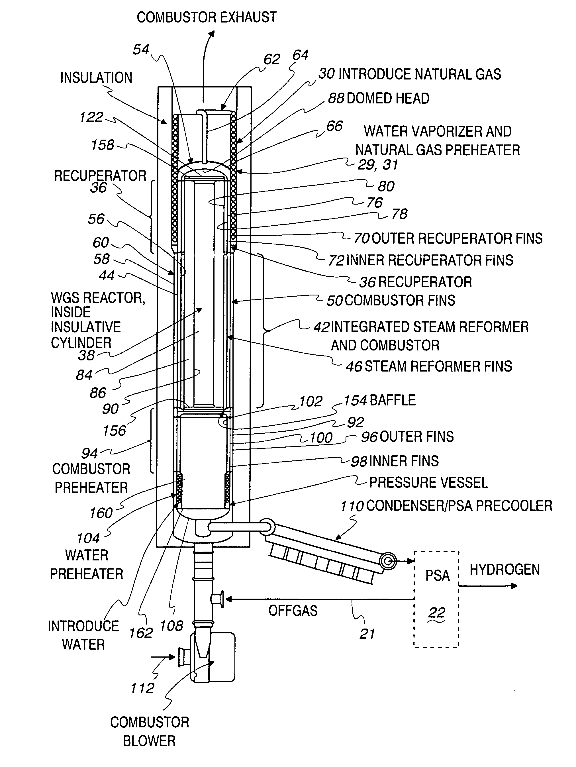
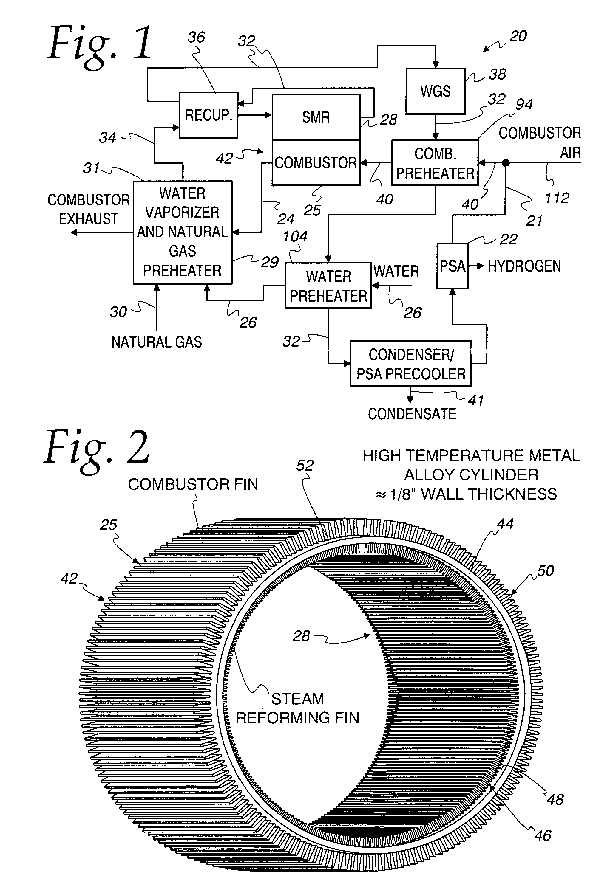
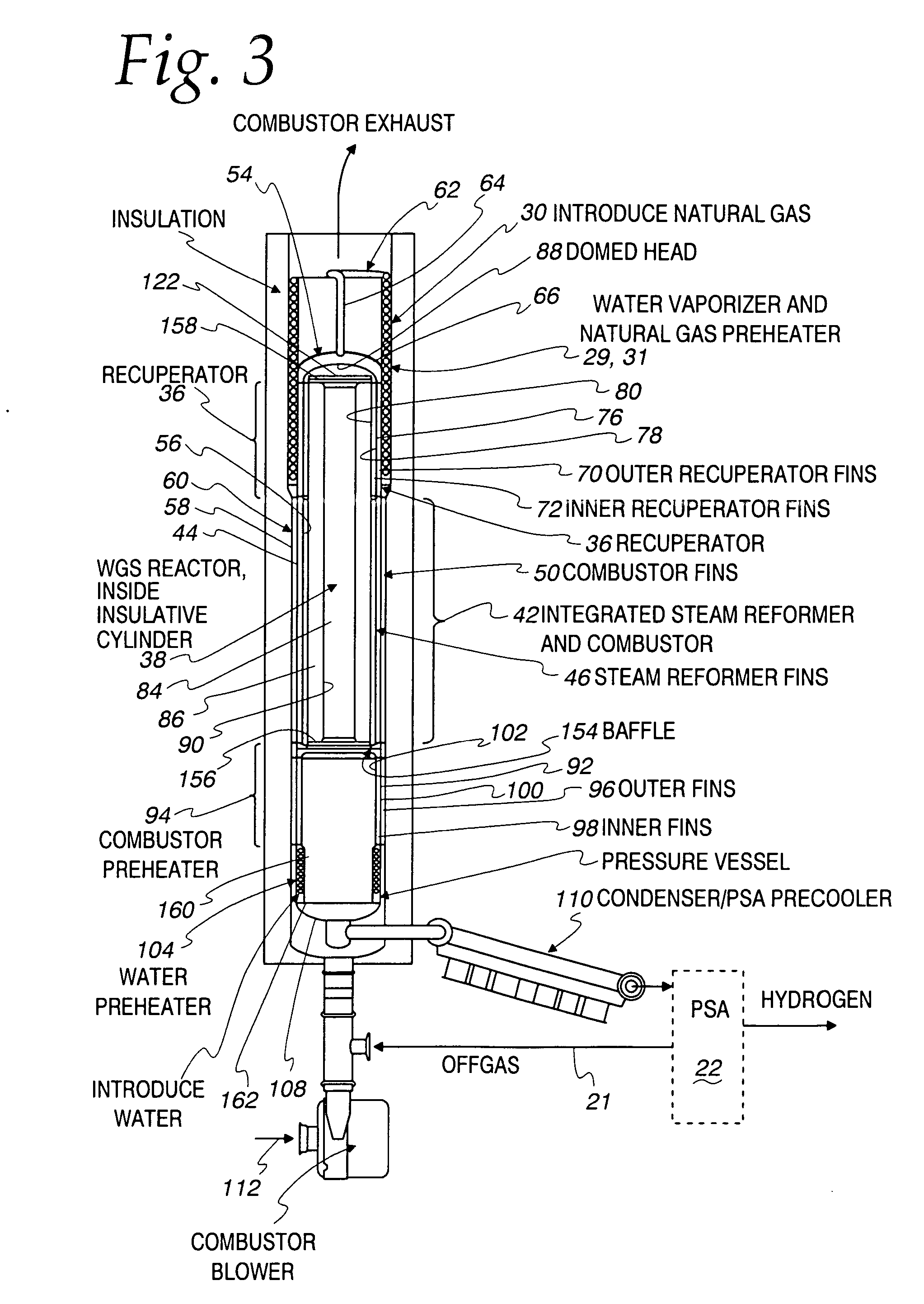
[0044] A system schematic of a highly integrated fuel processor 20 is shown in FIG. 1. In this system, the only source of fuel required for the combustor is the hydrogen-depleted off-gas 21 from the Pressure Swing Absorption (PSA) unit 22. The high-pressure side of the PSA 22 is preferably designed to operate at 100 psig, while the low-pressure side of the PSA is designed to operate at near-atmospheric pressure (˜1 psig). Heat recovered from a combustor exhaust 24 of combustor 25 is used in a vaporizer 29 to vaporize and superheat a water feed 26 for a steam reformer 28, as well as to preheat a natural gas feed 30 for the steam reformer 28 in a fuel preheater 31. Heat is recovered from a reformate stream 32 exiting the steam reformer 28 and is used to further preheat the now mixed steam-natural gas feed 34 in a recuperative heat exchanger 36. A water-gas shift (WGS) reactor 38 is used to increase hydrogen production. Downstream of the water-gas shift reactor 38, additional heat is r...


PUM

PropertyMeasurementUnit
energyaaaaaaaaaa
energyaaaaaaaaaa
temperaturesaaaaaaaaaa

Abstract

A fuel processing system is provided wherein heat is transferred from a reformate flow (32) downstream from a water-gas shift (38) to both a) a combustor feed flow (40) that is supplied to a combustor (25); and b) a water flow (26) that is supplied to a reformer feed mix (34) for a steam reformer (28).

Description

FIELD OF THE INVENTION [0001] This invention relates to fuel processors, and in more particular applications to fuel processors for distributed hydrogen production. BACKGROUND OF THE INVENTION [0002] It has been well-established that a critical key to the long-term success of fuel cell vehicles is the development of a hydrogen infrastructure. Fuel cell vehicles are projected by many to be the eventual replacement of, or at the very least supplement to, the internal combustion engine vehicle. This is driven primarily by the growing concerns over greenhouse gas and air pollutant emissions, long-term availability of fossil fuels, and energy supply security. The proton exchange membrane (PEM) fuel cells which are the focus of almost all the current efforts towards the development of commercially viable fuel cell vehicles require hydrogen as a fuel. Virtually all efforts towards the on-board production of hydrogen from more portable hydrocarbon fuels have been abandoned in recent years, ...

Claims


Application Information

Patent Timeline
Patent Type & Authority Applications(United States)
IPC IPC(8): C10J1/207B01B1/00B01F1/00B01J8/04B01J19/00B01J19/24C01B3/16C01B3/32C01B3/34C01B3/38C01B3/48C01B3/56F22D1/38F28D7/02F28D7/10F28F1/10F28F1/42H01M8/04H01M8/06H01M8/10
CPCB01B1/005Y02E60/521B01J19/244B01J19/2485B01J19/249B01J2219/00006B01J2219/0004B01J2219/00083B01J2219/0009B01J2219/00103B01J2219/00117B01J2219/00155B01J2219/00157B01J2219/00159B01J2219/2455B01J2219/2458B01J2219/2459B01J2219/2464B01J2219/2465B01J2219/2466B01J2219/2467B01J2219/247B01J2219/2474B01J2219/2479B01J2219/2486C01B3/16C01B3/384C01B3/48C01B3/56C01B2203/0233C01B2203/0283C01B2203/042C01B2203/066C01B2203/0811C01B2203/0827C01B2203/0883C01B2203/0894C01B2203/1017C01B2203/1023C01B2203/1035C01B2203/12C01B2203/1294C01B2203/82F28D7/024F28D7/10F28D7/106F28F1/105F28F1/42H01M8/04022H01M8/0618H01M2008/1095Y02E60/50B01J12/007Y02P20/129B01J8/0465F22D1/38F28D7/02B01J8/04B01J19/00C01B3/38
Inventor REINKE, MICHAEL J.VALENSA, JEROENBANDHAUER, TODDSILER, NICHOLASVOSS, MARK G.MCGREGOR, MICHAELGRANETZKE, DENNIS C.
Owner MODINE MFG CO
Learn More