Evaporated fuel treatment device for internal combustion engine
a technology of evaporation fuel treatment and internal combustion engine, which is applied in the direction of combustion air/fuel air treatment, machines/engines, instruments, etc., can solve the problems of not taking into account the diagnostics of sealing valve failure of the above-conventional device, the inability to obtain desired evaporated fuel treatment capacity, and the inability to obtain desired refueling characteristics. , to achieve the effect of efficient and accura
- Summary
- Abstract
- Description
- Claims
- Application Information
AI Technical Summary
Benefits of technology
Problems solved by technology
Method used
Image
Examples
first embodiment
[Description of Structure of Device]
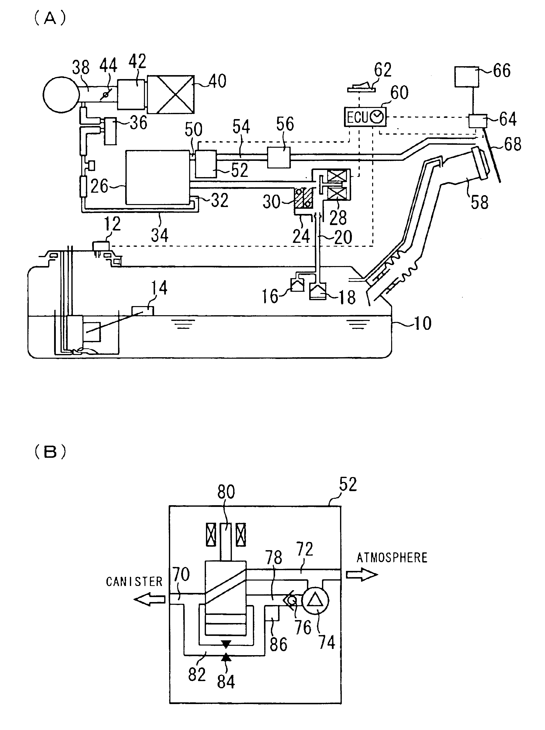
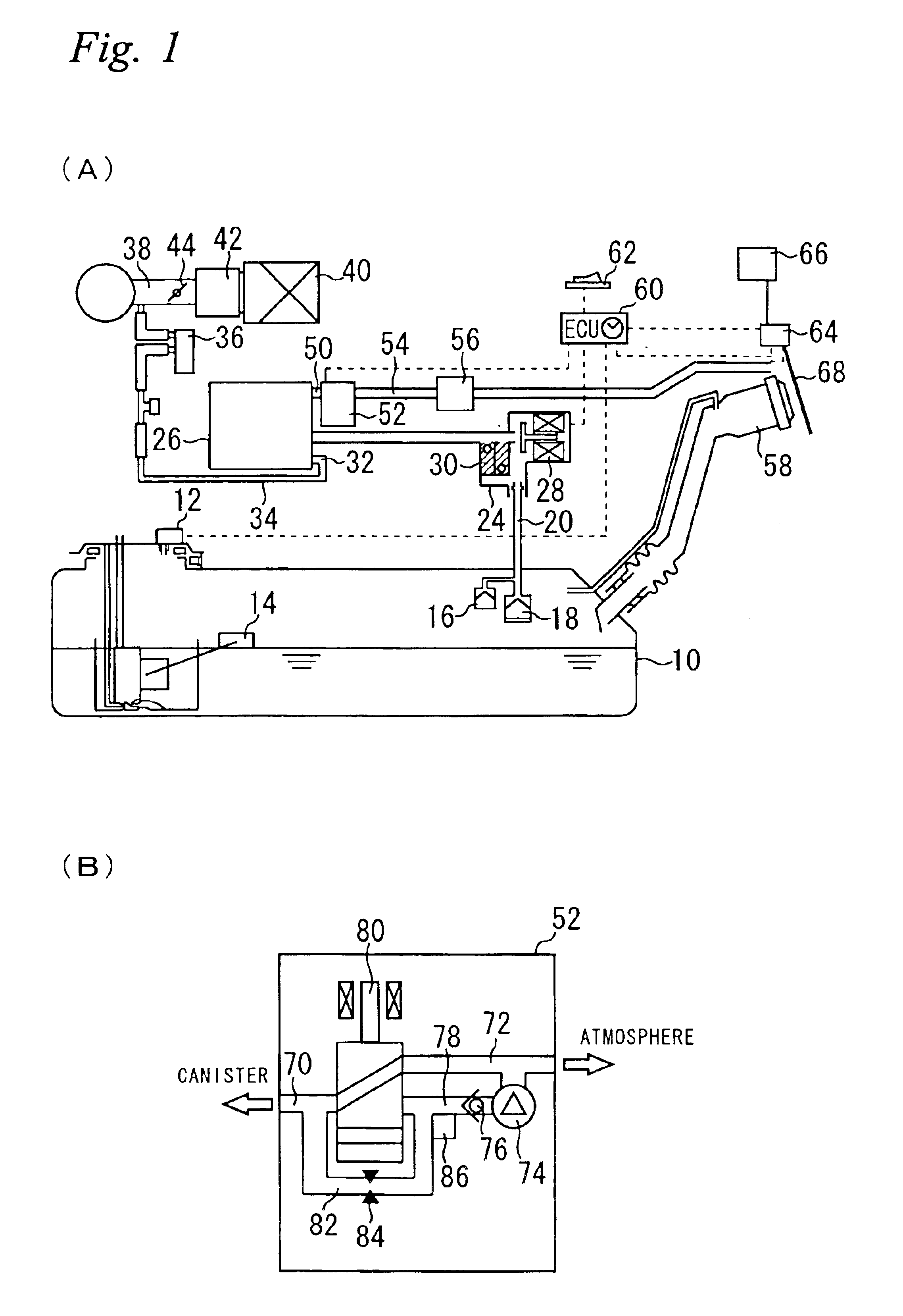
FIG. 1A illustrates a structure of an evaporated fuel treatment device according to a first embodiment of the invention. As shown in FIG. 1A, the device according to the present embodiment includes a fuel tank 10. The fuel tank 10 has a tank internal pressure sensor 12 for measuring tank internal pressure Pt. The tank internal pressure sensor 12 detects the tank internal pressure Pt as relative pressure with respect to atmospheric pressure, and generates output in response to a detection value. A liquid level sensor 14 for detecting a liquid level of fuel is placed in the fuel tank 10.
A vapor passage 20 is connected to the fuel tank 10 via ROVs (Roll Over Valves) 16, 18. The vapor passage 20 has a sealing valve unit 24 on the way thereof, and communicates with a canister 26 at an end thereof. The sealing valve unit 24 has a sealing valve 28 and a pressure control valve 30. The sealing valve 28 is a solenoid valve of a normally closed type, which i...
second embodiment
A second embodiment of the present invention will now be described with reference to FIG. 12. The evaporated fuel treatment device according to the present embodiment is implemented by modifying the evaporated fuel treatment device according to the first embodiment so as to execute a routine shown in FIG. 12, which will be described later, in place of the routine shown in FIG. 9.
FIG. 12 is a flowchart illustrating a routine that is executed by the ECU 60 to conduct an open failure diagnostic check on the sealing valve 28. This routine is the same as the one shown in FIG. 9 except that the step for judging whether an open failure has occurred in the sealing valve 28 is changed from step 200 to step 270. When the present embodiment is described in reference to FIG. 12, steps identical with those described in reference to FIG. 9 are designated by the same reference numerals as their counterparts and omitted from the description or briefly described.
In the routine shown in FIG. 12, a ch...
third embodiment
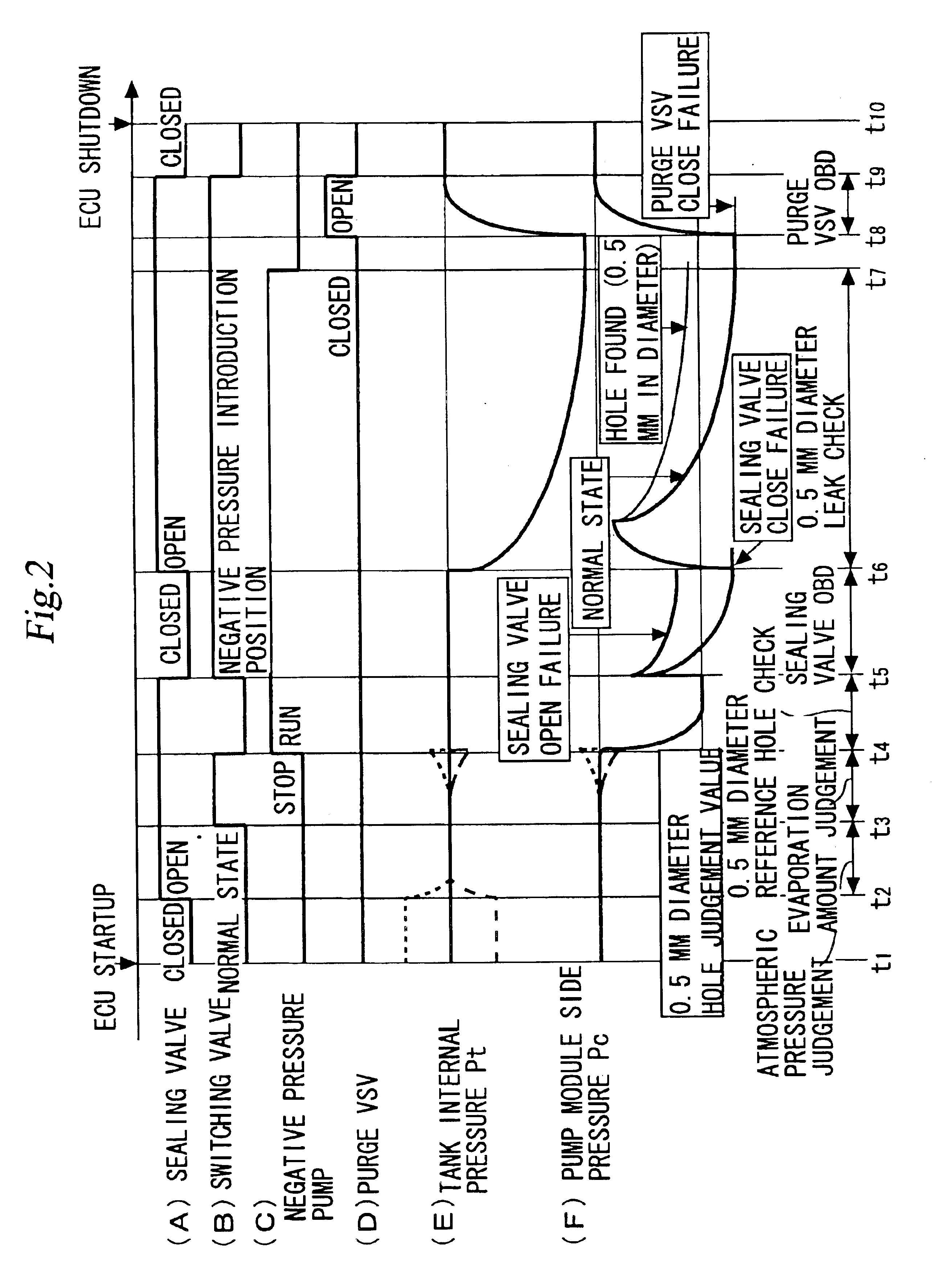
A third embodiment of the present invention will now be described with reference to FIGS. 13A through 16. FIGS. 13A through 13E are timing diagrams illustrating an abnormality detection process that is performed by the evaporated fuel treatment device of the present embodiment. The evaporated fuel treatment device according to the present embodiment is implemented by modifying the device according to the first embodiment such that the ECU 60 executes an abnormality detection process by following a sequence shown in FIG. 13. For the purpose of minimizing the influence of various disturbances, the abnormality detection process according to the present embodiment is performed while the vehicle is parked, as is the case with the first embodiment.
The abnormality detection process according to the present embodiment (in compliance with the sequence indicated in FIG. 13) is substantially the same as that is performed in accordance with the first embodiment (in compliance with the sequence ...
PUM
 Abstract
Description
Claims
Application Information
 - R&D
- Intellectual Property
- Life Sciences
- Materials
- Tech Scout
- Unparalleled Data Quality
- Higher Quality Content
- 60% Fewer Hallucinations
Browse by: Latest US Patents, China's latest patents, Technical Efficacy Thesaurus, Application Domain, Technology Topic, Popular Technical Reports.
© 2025 PatSnap. All rights reserved.Legal|Privacy policy|Modern Slavery Act Transparency Statement|Sitemap|About US| Contact US: help@patsnap.com


