A negative pressure filter system
A technology of negative pressure filtration and filter tube, which is applied in the direction of filtration separation, filtration circuit, separation method, etc., can solve the problems of water environmental pollution, high concentration, and uncontrollable concentration of harmful substances in wastewater, so as to reduce cleaning time and improve filtration Speed, improve the effect of rapid removal efficiency
- Summary
- Abstract
- Description
- Claims
- Application Information
AI Technical Summary
Problems solved by technology
Method used
Image
Examples
Embodiment 1
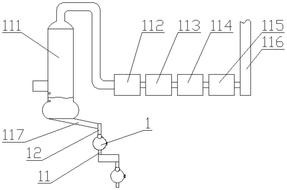
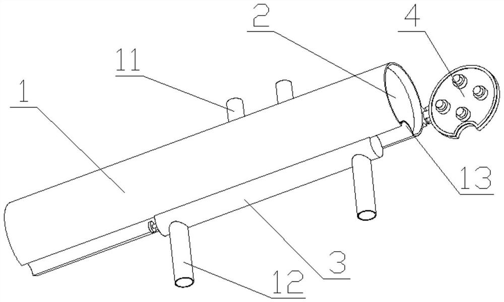
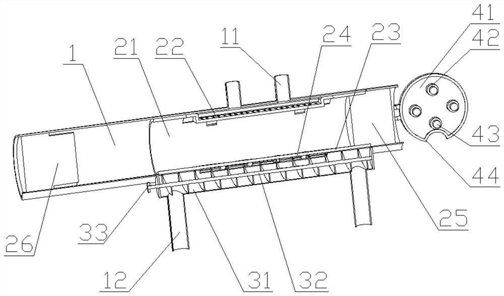
[0026] Such as Figure 1 to Figure 6Shown; A kind of negative pressure filter system, comprises spray tower 111, liquid guide pipe 117, air guide pipe and at least two negative pressure filter devices connected in series, and described spray tower 111 is connected successively by air guide pipe with Drying device 112, adsorption device 113, plasma generator 114, blower fan 115 and exhaust pipe 116, the bottom of described spray tower 111 is connected with negative pressure filter device by conduit 117, and described conduit 117 is provided with electric motor Ball valve, the spray tower 111 is located below the smoke inlet pipe and is provided with two liquid level sensors for controlling the liquid level; the negative pressure filter device includes a filter pipe 1, a filter device 2 and a controller, and the filter device 2 Set in the filter tube 1, one end of the filter tube 1 is provided with a pressure measuring and sealing mechanism 4, and the other end of the filter tub...
Embodiment 2
[0029] On the basis of Embodiment 1, the pressure measuring and sealing mechanism 4 includes a sealing door 41, and at least one pressure sensor 42 is arranged on the sealing door 41, and a buffer block 43 is arranged on the pressure sensor 42. The sealing door 41 is provided with a sealing gasket 44; the pressure sensor 42 is electrically connected to the controller; one side of the filter barrel 21 is provided with a filtered liquid door 22, and the filtered liquid door 22 is provided with a concave return cavity 27. The liquid outlet hole 28 is set on the concave return cavity 27; the filter barrel 21 is provided with an inner arc-shaped sliding wall 23 on one side, and the filter hole 24 is set in the inner arc-shaped sliding wall 23, and the filtering One side of the tube 1 is provided with an outer arc-shaped sliding wall 13 that cooperates with the inner arc-shaped sliding wall 23; the filter bucket 21 is provided with at least two sealing strips, and the sealing strips ...
Embodiment 3
[0032] On the basis of Example 2, the gap between the filter tube 1 and the filter bucket 21 is 0.5mm to 2.0mm, and the thickness of the sealing ring 29 is 10mm to 20mm; the sealing ring 29 is made of silica gel, and the silica gel The hardness is 20 degrees to 50 degrees; the screw rod 32 blades on one side of the filter hole 24 are provided with a slow pressure cleaning notch 34; the width of the slow pressure cleaning groove 34 is the width 1 / of the screw rod 32 blades 2.
[0033] By setting the gap between the filter tube 1 and the filter bucket 21 to 0.5mm to 2.0mm, the phenomenon of difficulty in installation can be avoided. If the gap is too large, the filter will also flow directly to the liquid outlet pipe 11; It is set to 10mm to 20mm, and the hardness is set to 20 degrees to 50 degrees, so that after the sealing ring 29 is under pressure, one side thereof will be squeezed and deformed so that the side surface contacts the inner wall of the filter tube 1 to achieve ...
PUM
| Property | Measurement | Unit |
|---|---|---|
| thickness | aaaaa | aaaaa |
| hardness | aaaaa | aaaaa |
Abstract
Description
Claims
Application Information
 - R&D
- Intellectual Property
- Life Sciences
- Materials
- Tech Scout
- Unparalleled Data Quality
- Higher Quality Content
- 60% Fewer Hallucinations
Browse by: Latest US Patents, China's latest patents, Technical Efficacy Thesaurus, Application Domain, Technology Topic, Popular Technical Reports.
© 2025 PatSnap. All rights reserved.Legal|Privacy policy|Modern Slavery Act Transparency Statement|Sitemap|About US| Contact US: help@patsnap.com


