
Cutting device used for aluminum alloy sheet material based on cutting space adjusting technology

A technology of aluminum alloy sheet and cutting device, which is applied to shearing device, attachment of shearing machine, metal processing equipment, etc., can solve the problems of decreased utilization rate of aluminum alloy sheet and increase of leftover materials, so as to improve cutting efficiency and improve utilization rate. rate, reducing the effect of scrap production

Inactive Publication Date: 2019-04-30
戎珊珊
View PDF6 Cites 5 Cited by
  • Summary
  • Abstract
  • Description
  • Claims
  • Application Information

AI Technical Summary

Problems solved by technology

However, the existing cutting device can only complete the processing by cutting an aluminum alloy plate multiple times, and the size of the plate needs to be cut twice on the cut standard block, resulting in an increase in leftover materials and a sharp drop in the utilization rate of the aluminum alloy plate

Method used


Image

  • Cutting device used for aluminum alloy sheet material based on cutting space adjusting technology
  • Cutting device used for aluminum alloy sheet material based on cutting space adjusting technology
  • Cutting device used for aluminum alloy sheet material based on cutting space adjusting technology

Examples


Embodiment 1

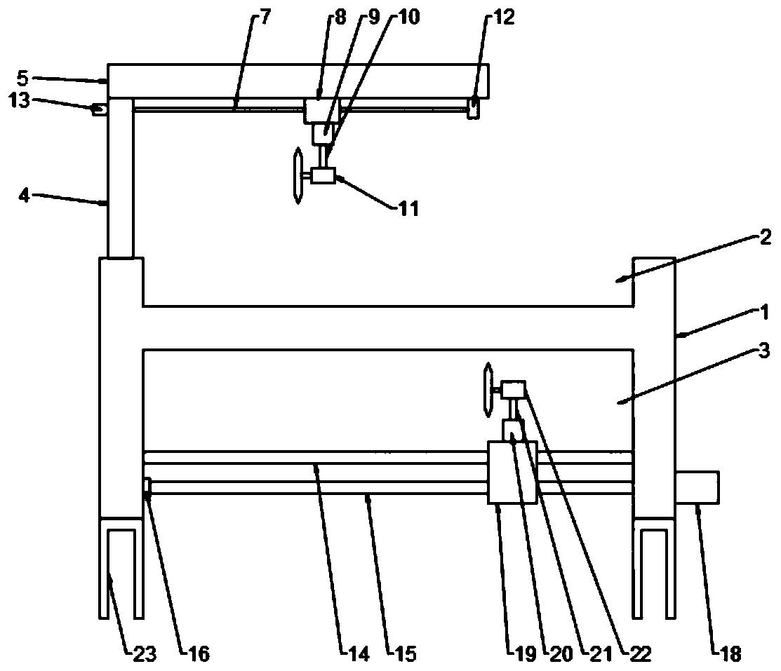
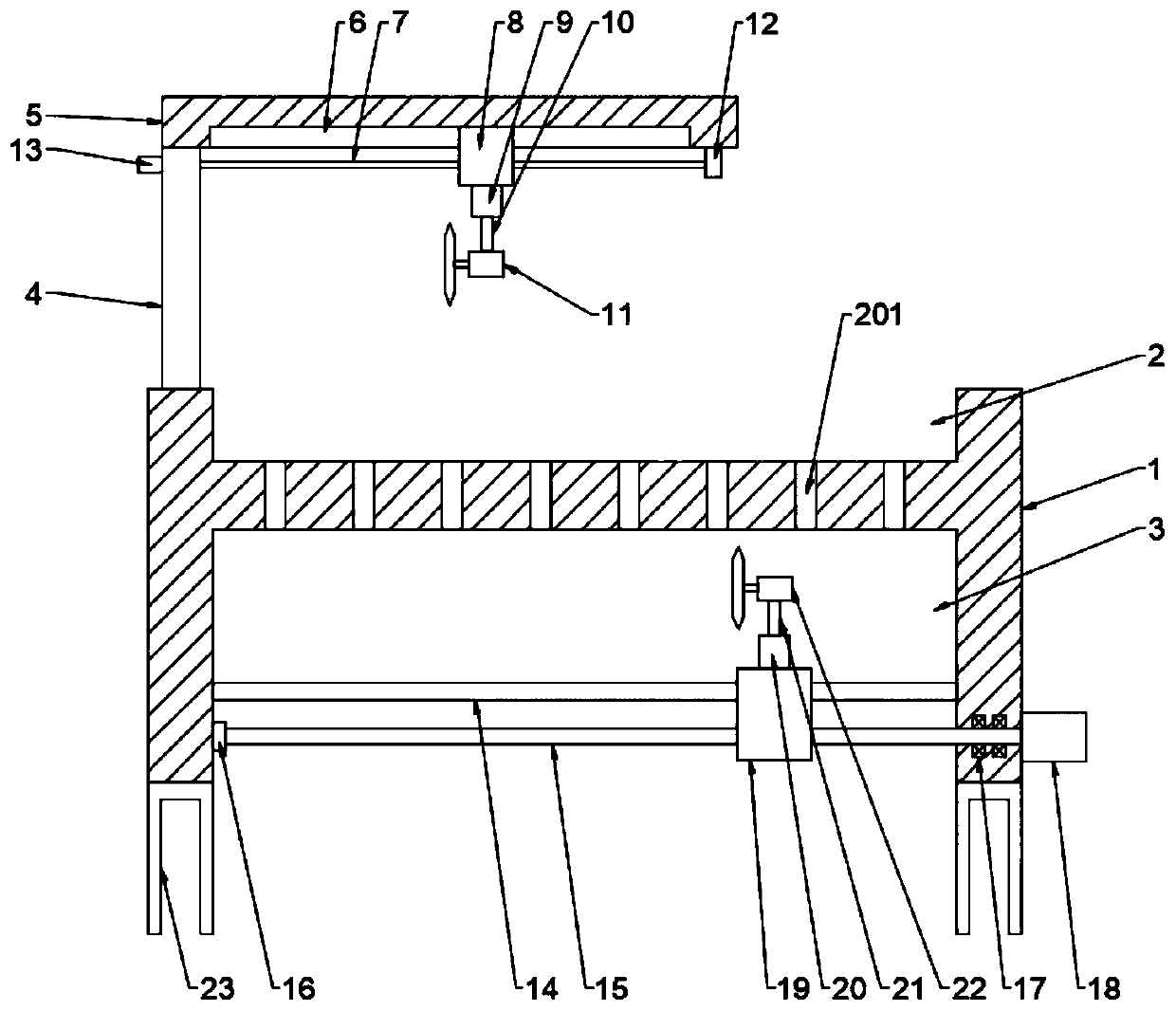
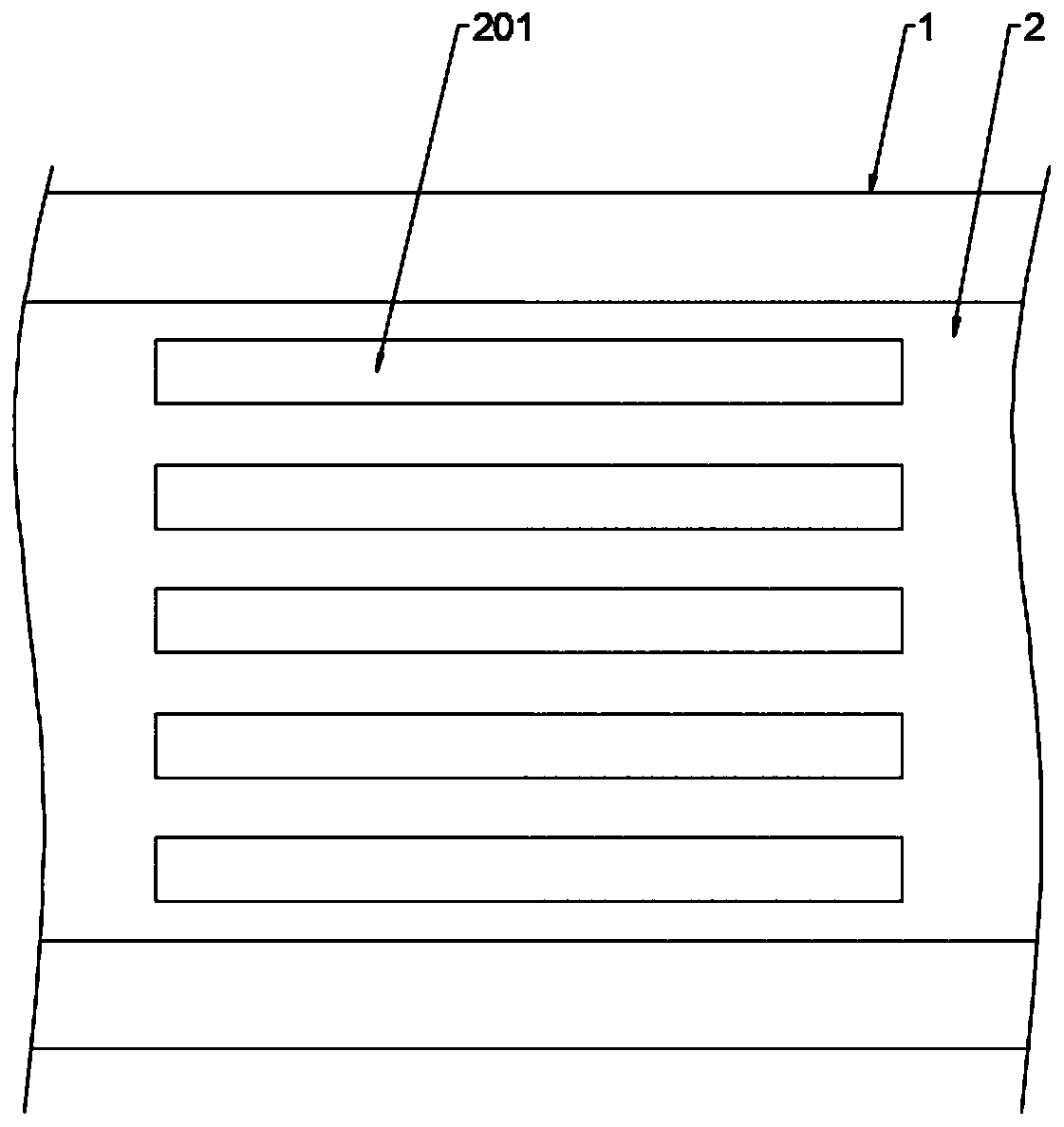
[0026] see Figure 1~3 , a cutting device for aluminum alloy sheets based on the technology of cutting spacing adjustment, comprising a seat frame 1, the top of the seat frame 1 is provided with a cutting groove 2, and the bottom wall of the inner cavity of the cutting groove 2 is uniformly provided with a number of cutting Holes 201, all the cutting holes 201 are arranged side by side and parallel to each other, the left side of the top of the cutting groove 2 is provided with a column 4, the top of the column 4 is provided with a beam 5, the length of the beam 5 is longer than the cutting 1 / 2 of the width of the groove 2, the beam 5 is provided with a first feeding mechanism, the first feeding mechanism is provided with a first cutting mechanism matched with the cutting hole 201, the bottom end of the seat frame 1 A bottom groove 3 is provided, and a second feeding mechanism is arranged in the bottom groove 3, and a second cutting mechanism matched with the cutting hole 201 ...

Embodiment 2

[0028] This embodiment is a further elaboration on the basis of Embodiment 1, the first feeding mechanism includes a chute 6, the chute 6 is arranged in the middle of the bottom end of the beam 5, and the chute 6 is a T-shaped slot, so The bottom of the crossbeam 5 is provided with an upper lead screw 7 matched with the chute 6, the relationship between the upper lead screw 7 and the chute 6 is parallel to each other, and the right end of the upper lead screw 7 passes through the upper bearing seat 12 Rotationally connected on the beam 5, the left end of the upper screw 7 runs through the column 4 and is fixedly connected to the upper motor 13, the upper screw 7 and the column 4 are connected in rotation, and the upper motor 13 is fixedly connected to the column 4 Go up, start motor 13, can drive upper leading screw 7 high-speed rotations.

[0029] Said upper screw 7 is provided with an upper moving seat 8 matched with the chute 6, the upper moving seat 8 and the upper screw 7...

Embodiment 3

[0032]This embodiment is a further elaboration on the basis of Embodiment 1. The second feeding mechanism includes a slide bar 14, the slide bar 14 is arranged on the inner cavity bottom wall of the bottom groove 3, and the slide bar 14 is provided with The lower leading screw 15, the slide bar 14 and the lower leading screw 15 are parallel to each other. The left side end of the lower leading screw 15 is connected to the inner cavity side wall of the bottom groove 3 through the lower bearing seat 16. The lower leading screw The right end of 15 runs through the right side wall of the inner chamber of the bottom groove 3 and is fixedly connected to the lower motor 18, the lower screw 15 is connected to the bottom groove 3 through the bearing 17 in rotation, and the lower motor 18 is fixedly connected to the seat frame 1, Starting the lower motor 18 can drive the lower leading screw 15 to rotate at a high speed.

[0033] The lower screw 15 is sleeved with a lower moving seat 19 ...


PUM


Abstract

The invention provides a cutting device used for an aluminum alloy sheet material based on a cutting space adjusting technology. The cutting device used for the aluminum alloy sheet material based onthe cutting space adjusting technology is particularly used for the technical field of aluminum alloy sheet material machining. The cutting device used for the aluminum alloy sheet material based on the cutting space adjusting technology comprises a seat frame. A cutting groove is formed in the top end of the seat frame, a plurality of cutting holes are uniformly formed in the inner cavity bottomwall of the cutting groove, a vertical column is arranged on the left side of the top end of cutting groove, a horizontal beam is arranged at the top end of the vertical column, the horizontal beam isprovided with a first feeding mechanism, the first feeding mechanism is provided with a first cutting mechanism, a bottom groove is formed in the bottom end of the seat frame, a second feeding mechanism is arranged in the bottom groove, and the second feeding mechanism is provided with a second cutting mechanism. According to the cutting device used for the aluminum alloy sheet material based onthe cutting space adjusting technology, an upper lead screw is matched with a sliding groove, and thus the position of the first cutting device is adjusted; and meanwhile a lower lead screw is matchedwith a sliding rod, so that the position of a second cutting device is adjusted, thus the cutting space distance is adjusted, two or three aluminum alloy sheet materials with the same specification can be cut at the same time, two or three aluminum alloy sheet materials with the different specification can also be cut at the same time, thus the cutting time can be greatly lowered, and the cuttingefficiency is improved.

Description

technical field [0001] The invention relates to the technical field of aluminum alloy plate processing, in particular to a cutting device for aluminum alloy plate based on cutting distance adjustment technology. Background technique [0002] Aluminum alloy is the most widely used non-ferrous metal structural material in industry, and has been widely used in aviation, aerospace, automobile, machinery manufacturing, shipbuilding and chemical industry. With the rapid development of industrial economy, the demand for welded structural parts of aluminum alloy is increasing day by day, so that the research on weldability of aluminum alloy is also in-depth. [0003] In the process of using aluminum alloy, it mostly appears in the form of pipes and plates. In the process of using a large number of plates, it is necessary to use a cutting device to cut them into small pieces of aluminum alloy plates for use. However, the existing cutting device can only complete the processing by cu...

Claims


Application Information

Patent Timeline
Patent Type & Authority Applications(China)
IPC IPC(8): B23D19/06B23D33/00
CPCB23D19/06B23D33/00
Inventor 戎珊珊
Owner 戎珊珊
Learn More