
A self-adaptive fixture for pipeline welding

A tooling fixture and self-adaptive technology, applied in welding equipment, manufacturing tools, auxiliary welding equipment, etc., can solve the problems of inability to accurately adjust the welding angle of the pipeline, unstable fixing of the pipeline shell, troublesome adjustment of the welding fixture, etc., and achieve easy promotion Use, innovative design, and the effect of improving welding quality

Active Publication Date: 2021-09-21
CHONGQING UNIVERSITY OF SCIENCE AND TECHNOLOGY
View PDF14 Cites 2 Cited by
  • Summary
  • Abstract
  • Description
  • Claims
  • Application Information

AI Technical Summary

Problems solved by technology

However, due to the smoothness of the outer wall of the pipe during welding, it is difficult to fix it, and the fixing tooling of the pipe is not stable to the pipe shell, so it is easy to shake when the pipe shell is welded, resulting in poor welding quality, which often fails to meet expectations In addition, the existing pipe welding fixture is troublesome to adjust, cannot adapt to pipes of different diameters, cannot accurately adjust the welding angle of the pipe, and has poor clamping stability

Method used


Image

  • A self-adaptive fixture for pipeline welding
  • A self-adaptive fixture for pipeline welding
  • A self-adaptive fixture for pipeline welding

Examples


Embodiment 1

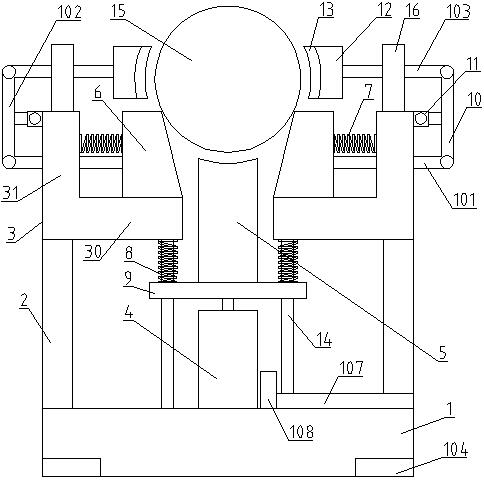
[0033] Such as figure 1 As shown, a pipeline welding self-adaptive fixture of the present invention includes a base 1, a support column 2 and an installation block 3, the support column 2 is arranged at both ends of the base 1, and the installation block 3 is arranged on the support column 2, and the installation A support space is provided between the blocks 3, and a jack post 5 for placing the pipeline 15 is arranged in the support space, and an oil cylinder 4 is arranged on the base 1, and the jack post 5 is connected to the top shaft of the oil cylinder 4 through a guide mechanism; the setting of the guide mechanism It can effectively guide the movement direction of the top column 5, avoid misalignment, and ensure precise operation during movement. The lifting and lowering of the jacking column 5 is realized by the telescoping of the jacking shaft of the oil cylinder 4 so as to realize the lifting and lowering of the pipeline 15 .

[0034] The mounting block 3 includes a ...

Embodiment 2

[0042] Such as Figure 4 As shown, the difference between this embodiment and Embodiment 1 is that the longitudinal corner block 31 also includes a support block 16 arranged on its top, and the clamping section 103 slides through the support block 16 and the locking sleeve 161 on the support block 16 set on the support block 16. The outer diameter of the locking sleeve 161 shrinks away from the support block 16. The locking sleeve 161 is provided with a number of scaling grooves 163 that facilitate the scaling of the locking sleeve 161. The locking sleeve 161 is threadedly connected with a compression ring. 162.

[0043] In use, when the pipe is clamped and the pressure ring 162 is twisted, the pressure of the pressure ring 162 on the locking sleeve 161 gradually increases due to the diameter change of the locking sleeve 161 . At the same time, the positive pressure of the locking sleeve 161 on the clamping section 103 also increases, and the relative friction between the lo...

Embodiment 3

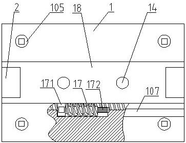
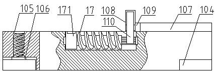
[0045] Such as figure 2 with 3 As shown, the base 1 also includes support legs 104, worm 17, sliding base 18 and adjustment cylinder 107; The guide rod 14 is arranged on the sliding base 18 , and the adjusting cylinder 107 is arranged on the base 1 parallel to the sliding base 18 .

[0046] One end of the adjustment cylinder 107 is connected with the gear cover 108 on the base 1 , and the adjustment cylinder 107 is provided with an adjustment ball 109 connected with the driving gear 110 , and the driving gear 110 is arranged in the gear cover 108 .

[0047] The worm 17 is arranged in the base 1 and connected with the sliding base 18; one end of the worm 17 is connected with the adjusting collar 171 through a ratchet, and the other end is provided with a driven gear 172 with a smaller diameter, and the driven gear 172 cooperates with the driving gear 110 connect.

[0048] An adjusting screw 105 is connected to the supporting leg 104 , the adjusting screw 105 passes through ...


PUM


Abstract

The invention discloses a pipeline welding self-adapting fixture, relates to the technical field of pipeline welding, and provides a pipeline welding self-adapting fixture with high clamping stability and wide adaptability. It includes a base, support columns and installation blocks, the support columns are arranged at both ends of the base, the installation blocks are arranged on the support columns, a support space is provided between the installation blocks, and the support space is provided for placing The top column of the pipeline, the base is provided with an oil cylinder, and the top column is connected to the top shaft of the oil cylinder through a guide mechanism; the pipeline to be welded can be fixedly clamped by the clamping device, which greatly improves the pipeline welding process. The stability of the pipe effectively improves the welding effect of the pipe. By setting the sliding slant block, it can adapt to the clamping of pipes of different diameters and has wide adaptability. Improve the welding quality of the pipeline, and facilitate popularization and use.

Description

technical field [0001] The invention relates to the technical field of pipeline welding, in particular to a self-adaptive fixture for pipeline welding. Background technique [0002] Welding: also known as welding and welding, is a manufacturing process and technology for joining metal or other thermoplastic materials such as plastics by means of heating, high temperature or high pressure. There are many sources of energy for modern welding, including gas flames, electric arcs, lasers, electron beams, friction, and ultrasound. However, due to the smoothness of the outer wall of the pipe during welding, it is difficult to fix it, and the fixing tooling of the pipe is not stable to the pipe shell, so it is easy to shake when the pipe shell is welded, resulting in poor welding quality, which often fails to meet expectations In addition, the existing pipe welding fixtures are cumbersome to adjust, cannot adapt to pipes of different diameters, cannot accurately adjust the welding...

Claims


Application Information

Patent Timeline
Patent Type & Authority Patents(China)
IPC IPC(8): B25B11/00
CPCB23K37/0533
Inventor 王刚徐永庚张中文尹立孟姚宗湘
Owner CHONGQING UNIVERSITY OF SCIENCE AND TECHNOLOGY
Learn More