Supercharge Your Innovation With Domain-Expert AI Agents!

Current Intensity Regulating Device for Charged Particle Beam

A charged particle beam and regulating device technology, applied in multiple discharge path tubes and other directions, can solve problems such as slow thermal process, difficulty in achieving linear control, and hysteresis in the performance change from filament heating to beam current.

Active Publication Date: 2021-03-26
SHANGHAI AIPUQIANG PARTICLE EQUIP
View PDF5 Cites 0 Cited by
  • Summary
  • Abstract
  • Description
  • Claims
  • Application Information

AI Technical Summary

Problems solved by technology

Due to the relatively slow thermal process of the material, the performance change from filament heating to beam current will lag behind, and it is difficult to achieve linear control of output at a certain level

Method used


Image

  • Current Intensity Regulating Device for Charged Particle Beam
  • Current Intensity Regulating Device for Charged Particle Beam
  • Current Intensity Regulating Device for Charged Particle Beam

Examples


Embodiment 1

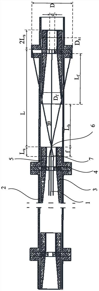
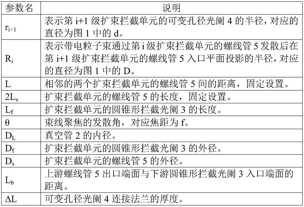
[0039] like figure 1 As shown, the structural schematic diagram of the current intensity adjustment device of the charged particle beam in this embodiment, the current intensity adjustment device of the charged particle beam includes a vacuum tube 2 and an N-level beam expander interception unit, and the N is a positive value greater than or equal to 2 Integer; In the present embodiment, N is 4 ( figure 1 Only the 3-stage beam expander interception unit is shown in ).

[0040] In the vacuum tube 2 along the forward direction of the charged particle beam 1 ( figure 1 , the charged particle beam 1 advances in order from left to right) the beam expander and interception units are arranged sequentially;

[0041] The beam expander interception unit includes: a conical interception diaphragm 3, a variable aperture diaphragm 4 and a solenoid 5;

[0042] The conical interception diaphragm 3 , the variable aperture diaphragm 4 and the solenoid 5 are sequentially arranged in the beam...


PUM


Abstract

The invention discloses a flow intensity adjustment device for a charged particle beam. The flow intensity adjustment device for a charged particle beam includes a vacuum tube and N stages of beam expanding intercepting unit, wherein the N is a positive integer greater than or equal to 2. The beam expanding intercepting units are arranged in the vacuum beam in order along the forward direction ofthe charged particle beam. Each beam expanding intercepting unit includes a conical interception diaphragm, a diaphragm with variable aperture and a solenoid. Each conical interception diaphragm, diaphragm with variable aperture and solenoid are arranged in the corresponding beam expanding intercepting unit in order along the forward direction of the charged particle beam. The charged particle beam passes through the N stages of beam expanding intercepting unit after entering the vacuum tube. The N stages of beam expanding intercepting unit attenuates the charged particle beam by magnitude. The flow intensity adjustment device for a charged particle beam realizes the high-precision cross-level adjustment of the flow intensity of the charged particle beam.

Description

technical field [0001] The invention relates to the field of transmission of charged particle beams, in particular to a device for adjusting the current intensity of charged particle beams. Background technique [0002] In the field of research and application of particle irradiation technology, due to the different materials, shapes and dose requirements of the irradiated objects, it is necessary to generate beams with different intensities. The means of adjusting the current intensity include the emission limitation of the particle source, the slit blocking or the setting of the working pulse width of the beam. When the particle source is an electron gun, as shown in the following formula, the parameters whose output can be adjusted include cathode temperature and grid potential. [0003] [0004] During controlled heating of the cathode, the temperature rises and falls to increase or decrease electron emission. Due to the relatively slow thermal process of the materi...

Claims


Application Information

Patent Timeline
Patent Type & Authority Patents(China)
IPC IPC(8): H01J21/26
CPCH01J21/26
Inventor 何子锋欧阳联华李德明
Owner SHANGHAI AIPUQIANG PARTICLE EQUIP
Features
  • R&D
  • Intellectual Property
  • Life Sciences
  • Materials
  • Tech Scout
  • Unparalleled Data Quality
  • Higher Quality Content
  • 60% Fewer Hallucinations
Learn More