Push-pull device for welding fixture

A welding fixture, push-pull device technology, applied in auxiliary devices, manufacturing tools, welding equipment and other directions, can solve the problems of employee discomfort, push-pull labor, increased physical consumption, etc., to save physical strength, facilitate pushing, and save space.

Pending Publication Date: 2019-05-03
HANTENG AUTOMOBILE CO LTD
View PDF0 Cites 0 Cited by
  • Summary
  • Abstract
  • Description
  • Claims
  • Application Information

AI Technical Summary

Problems solved by technology

However, due to the limited movable range of the spot welding gun, sometimes it is necessary to push and switch the fixture to move the welding fixture to a suitable position for welding
[0003] At present, there are still some problems in the existing push-pull device: 1. Since the push rod device is fixedly connected on the welding fixture, due to the different heights of the employees, if the height of the push-pull device cannot be changed, it will cause discomfort to the employees when pushing and pulling , increase physical exertion; 2. If the push-pull device is too short, it will make pushing and pulling more laborious, but if the push-pull device is too long, the push-pull device will affect the movement of other equipment after pushing and pulling, and there will be unnecessary troubles

Method used


Image

  • Push-pull device for welding fixture
  • Push-pull device for welding fixture
  • Push-pull device for welding fixture

Examples


Embodiment Construction

[0021] The following will clearly and completely describe the technical solutions in the embodiments of the present invention with reference to the accompanying drawings in the embodiments of the present invention. Obviously, the described embodiments are only some, not all, embodiments of the present invention. Based on the embodiments of the present invention, all other embodiments obtained by persons of ordinary skill in the art without making creative efforts belong to the protection scope of the present invention.

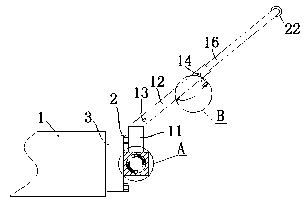
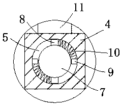
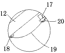
[0022] see Figure 1-6 , the present invention provides a technical solution: a push-pull device for a welding fixture, including a welding fixture 1, one side of the welding fixture 1 is fixedly connected with a connecting block 3 through a bolt 2, and the connecting block 3 is arranged symmetrically On both sides of the welding fixture 1, the connecting block 3 is welded with a fixing block 4, and the fixing block 4 is welded on both ends of the connecting b...


PUM


Abstract

The invention discloses a push-pull device for a welding fixture. The push-pull device for the welding fixture comprises a welding fixture body, connecting blocks are arranged on one side of the welding fixture body, fixed blocks are welded to each connecting block, and rotating shafts are rotatably arranged on the fixed blocks through bearings. First protrusion blocks are symmetrically welded tothe end parts of the rotating shafts, second protrusion blocks are welded into annular grooves, and springs are fixedly connected between the first protrusion blocks and the second protrusion blocks.Rotating rods are welded to the rotating shafts, first push-pull rods are welded to the rotating rods, and second push-pull rods are arranged on the first push-pull rods. According to the push-pull device for the welding fixture, when an employee pulls the second push-pull rods, the rotating shafts rotate through the action of the bearings, so that the second push-pull rods rotate to a position where is most suitable for the employee to push and pull; and meanwhile, the rotating shafts drive the first protrusion blocks to rotate to the second protrusion blocks, the springs are compressed, whenthe second push-pull rods are loosened, the springs automatically rotate the rotating shafts to an original position, and the reset of the second push-pull rods is realized.

Description

technical field [0001] The invention belongs to the technical field of push-pull devices for welding fixtures, in particular to a push-pull device for welding fixtures. Background technique [0002] In the automobile welding workshop, in order to assemble and weld multiple highly deformable stamping parts into high-precision body sub-assemblies, it is necessary to use a large number of suitable welding fixtures. However, due to the limited movable range of the spot welding torch, sometimes it is necessary to push and switch the fixture to move the welding fixture to a suitable position for welding. [0003] At present, there are still some problems in the existing push-pull device: 1. Since the push rod device is fixedly connected on the welding fixture, due to the different heights of the employees, if the height of the push-pull device cannot be changed, it will cause discomfort to the employees when pushing and pulling , increase physical exertion; 2, if the push-pull de...

Claims


Application Information

Patent Timeline
Patent Type & Authority Applications(China)
IPC IPC(8): B23K37/00
Inventor 刘鑫汪伟
Owner HANTENG AUTOMOBILE CO LTD
Why Eureka
Try Eureka