Bench frame welding auxiliary device

A technology of auxiliary device and stool, applied in welding/cutting auxiliary equipment, auxiliary device, welding equipment and other directions, can solve the problems of high labor cost, easy hand shaking, trouble, etc., and achieve the effect of improving work efficiency and facilitating welding

Inactive Publication Date: 2019-05-03
JIANGXI COLLEGE OF APPLIED TECH
View PDF6 Cites 1 Cited by
  • Summary
  • Abstract
  • Description
  • Claims
  • Application Information

AI Technical Summary

Problems solved by technology

[0002] In daily life, when people are tired and need to sit down and rest, they need to use a stool. The manufacture of the stool requires three U-shaped frames to be welded into a stool frame, and then follow-up processing. Usually, people press the U-shaped frame with their hands. The frame is fixed and then welded. After a long time, the hand shakes easily and affects the welding effect, and people need to move to weld the U-shaped frame. so high labor cost

Method used


Image

  • Bench frame welding auxiliary device
  • Bench frame welding auxiliary device
  • Bench frame welding auxiliary device

Examples


Embodiment 1

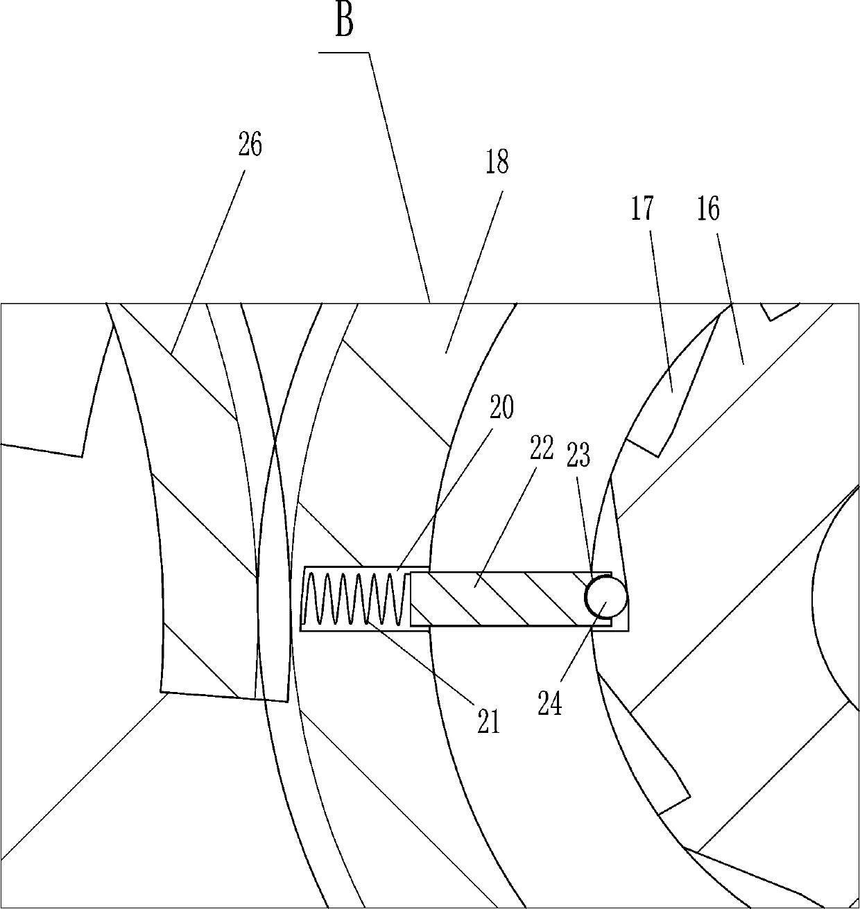
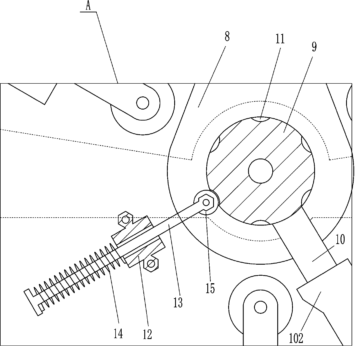
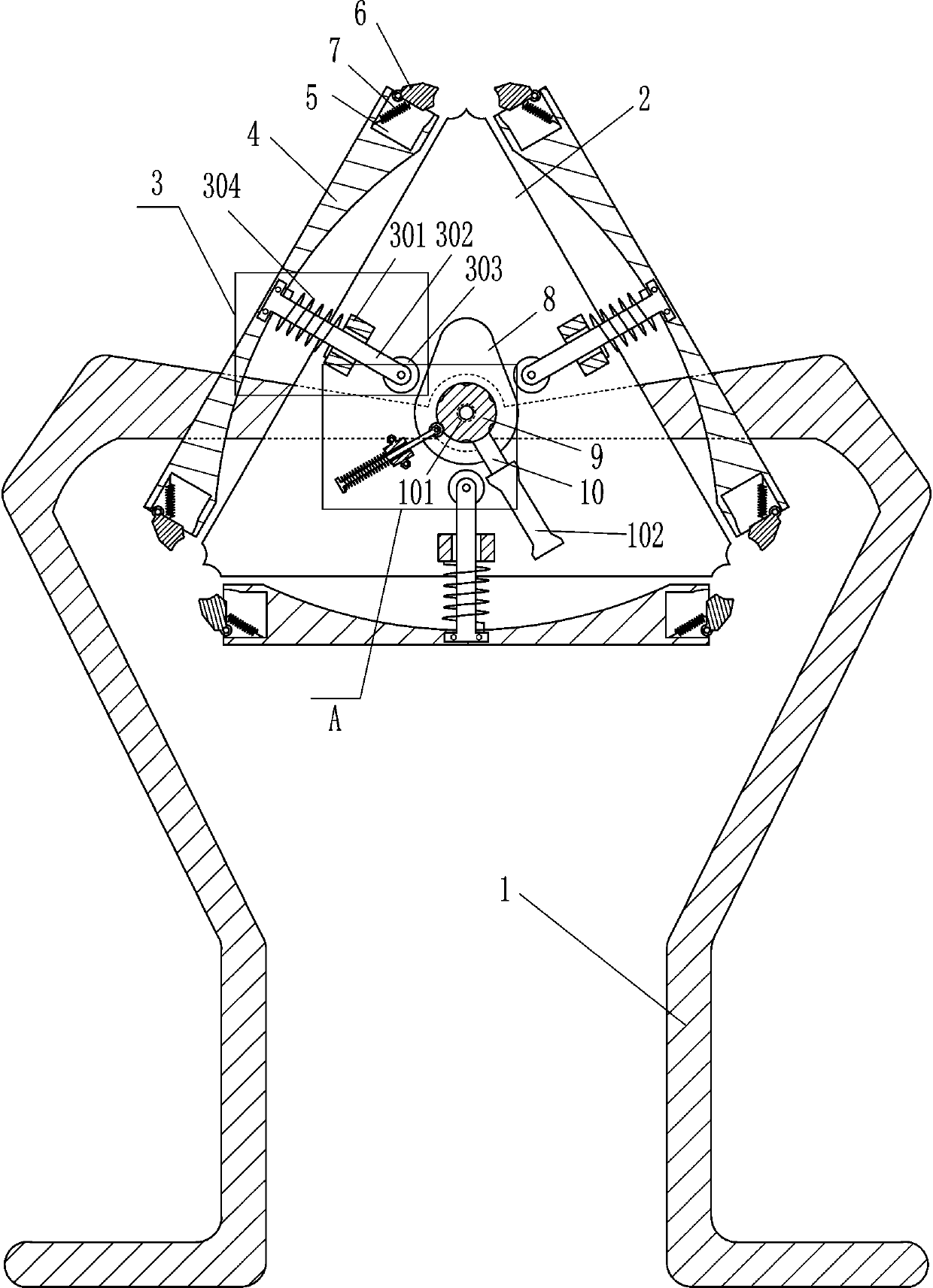
[0017] A stool frame welding aid such as figure 1 As shown, it includes a bracket 1, a rotating shaft 101, a first fixed plate 2, a telescopic device 3, a second fixed plate 4, a swing block 6, a second spring 7, a cam 8, a first turntable 9, a fixed rod 10 and rubber Sleeve 102, the upper middle part of bracket 1 is provided with rotating shaft 101, the front end of rotating shaft 101 is fixedly connected with the first fixed plate 2, the rotating shaft 101 is connected with the first fixed plate 2 by welding, the upper part of the front side of the first fixed plate 2 The left and right sides and the middle of the lower part are provided with telescopic devices 3, and each telescopic device 3 is provided with a second fixed plate 4, and both ends of the second fixed plate 4 are provided with guiding grooves 5, the grooves 5 The inner surface of the rotating type is provided with a swing block 6 that can fix the U-shaped frame. A second spring 7 is connected between the inner...

Embodiment 2

[0019] A stool frame welding aid such as figure 1 As shown, it includes a bracket 1, a rotating shaft 101, a first fixed plate 2, a telescopic device 3, a second fixed plate 4, a swing block 6, a second spring 7, a cam 8, a first turntable 9, a fixed rod 10 and rubber Cover 102, the upper middle of the bracket 1 is provided with a rotating shaft 101, the front end of the rotating shaft 101 is fixedly connected with the first fixed plate 2, and the first fixed plate 2 is provided with a telescopic device 3 on the upper, left, and right sides of the front side and in the middle of the lower part. The telescopic device 3 is provided with a second fixed plate 4, the two ends of the second fixed plate 4 are provided with guiding grooves 5, and the inner surface of the groove 5 is rotatably provided with a swing for fixing the U-shaped frame. Block 6, the second spring 7 is connected between the inner surface of the swinging block 6 and the inner surface of the groove 5, and the mid...

Embodiment 3

[0022] A stool frame welding aid such as Figure 1-2 As shown, it includes a bracket 1, a rotating shaft 101, a first fixed plate 2, a telescopic device 3, a second fixed plate 4, a swing block 6, a second spring 7, a cam 8, a first turntable 9, a fixed rod 10 and rubber Cover 102, the upper middle of the bracket 1 is provided with a rotating shaft 101, the front end of the rotating shaft 101 is fixedly connected with the first fixed plate 2, and the first fixed plate 2 is provided with a telescopic device 3 on the upper, left, and right sides of the front side and in the middle of the lower part. The telescopic device 3 is provided with a second fixed plate 4, the two ends of the second fixed plate 4 are provided with guiding grooves 5, and the inner surface of the groove 5 is rotatably provided with a swing for fixing the U-shaped frame. Block 6, the second spring 7 is connected between the inner surface of the swinging block 6 and the inner surface of the groove 5, and the ...


PUM


Abstract

The invention relates to an auxiliary device, in particular to a bench frame welding auxiliary device. According to the bench frame welding auxiliary device, U-shaped frames can be fixed, welding is facilitated to people without affecting the welding effect, and people do not need to continuously move. The bench frame welding auxiliary device comprises a bracket, a rotating shaft, a first fixing plate and the like, wherein the rotating shaft is rotatably arranged at the middle of the upper part of the bracket, and the first fixing plate is fixedly connected at the front end of the rotating shaft. The U-shaped frames can be fixed through the actions of swinging clamping blocks and the first fixing plate, so that people can weld the U-shaped frames without manually pressing the U-shaped frames, and the welding effect is prevented from being influenced by hand shaking; welding positions of the U-shaped frames can be rotated to the upper part by rotating second fixing plates, so that people can weld conveniently; and people can more conveniently rotate the U-shaped frames through the action of a swinging handle, and the working efficiency is improved.

Description

technical field [0001] The invention relates to an auxiliary device, in particular to a stool frame welding auxiliary device. Background technique [0002] In daily life, when people are tired and need to sit down and rest, they need to use a stool. The manufacture of the stool requires three U-shaped frames to be welded into a stool frame, and then follow-up processing. Usually, people press the U-shaped frame with their hands. The frame is fixed and then welded. After a long time, the hand shakes easily and affects the welding effect, and people need to move to weld the U-shaped frame. Such high labor costs. Contents of the invention [0003] In order to overcome the shortcomings that the hands are fixed by the U-shaped frame and then welded. Over time, the hands are easy to shake and affect the welding effect, and people need to move to weld the U-shaped frame, which is troublesome. Therefore, the technical problem of the present invention is: The invention provides a...

Claims


Application Information

Patent Timeline
Patent Type & Authority Applications(China)
IPC IPC(8): B23K37/04
Inventor 萧笃飞谢华东王浦舟谢宝飞林通
Owner JIANGXI COLLEGE OF APPLIED TECH
Why Eureka
Try Eureka