
A door lock bracket structure

A bracket structure and door lock technology, which is applied in building locks, building structures, locks controlled by non-mechanical transmission, etc., can solve the problems of poor force bearing effect at the bottom of the bracket, bending deformation at the bottom of the bracket, and poor adjustment effect of the magnetic lock. Achieve the effects of improving the fixing and closing effect, increasing the force effect, and facilitating fixing

Active Publication Date: 2021-05-07
张作利
View PDF2 Cites 0 Cited by
  • Summary
  • Abstract
  • Description
  • Claims
  • Application Information

AI Technical Summary

Problems solved by technology

[0006] In order to solve the above technical problems, the present invention provides a door lock bracket structure to solve the existing similar door lock bracket; when the magnetic lock is installed and fixed, the adjustment effect of the magnetic lock at the bottom of the bracket is poor, and the silicon steel sheet of the magnetic lock cannot be effective. If it fits closely with the iron sheet installed on the door body, it will easily affect the locking effect of the magnetic lock, and the force effect on the bottom of the bracket is poor. During long-term use, the bottom of the bracket is prone to be bent and deformed due to excessive tension, affecting The problem of the effect of the magnetic lock and the iron sheet

Method used


Image

  • A door lock bracket structure
  • A door lock bracket structure
  • A door lock bracket structure

Examples


Embodiment

[0032] as attached figure 1 to attach Figure 8 Shown:

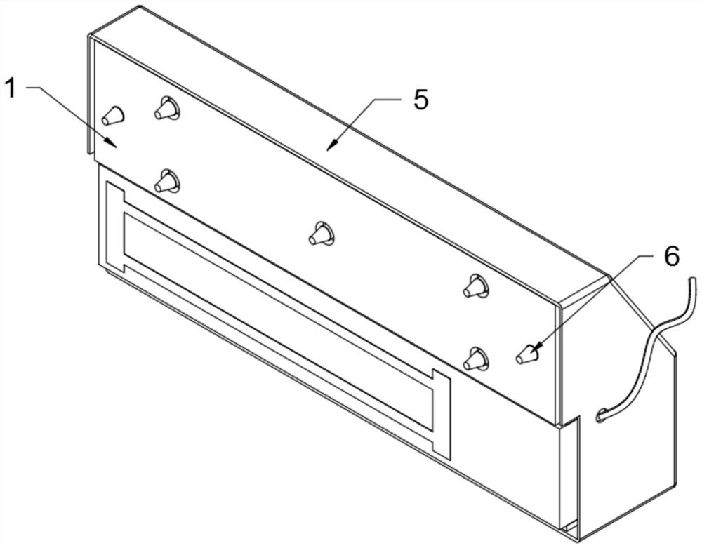
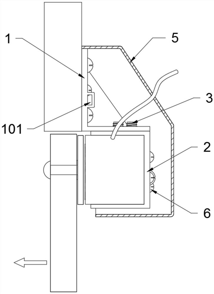
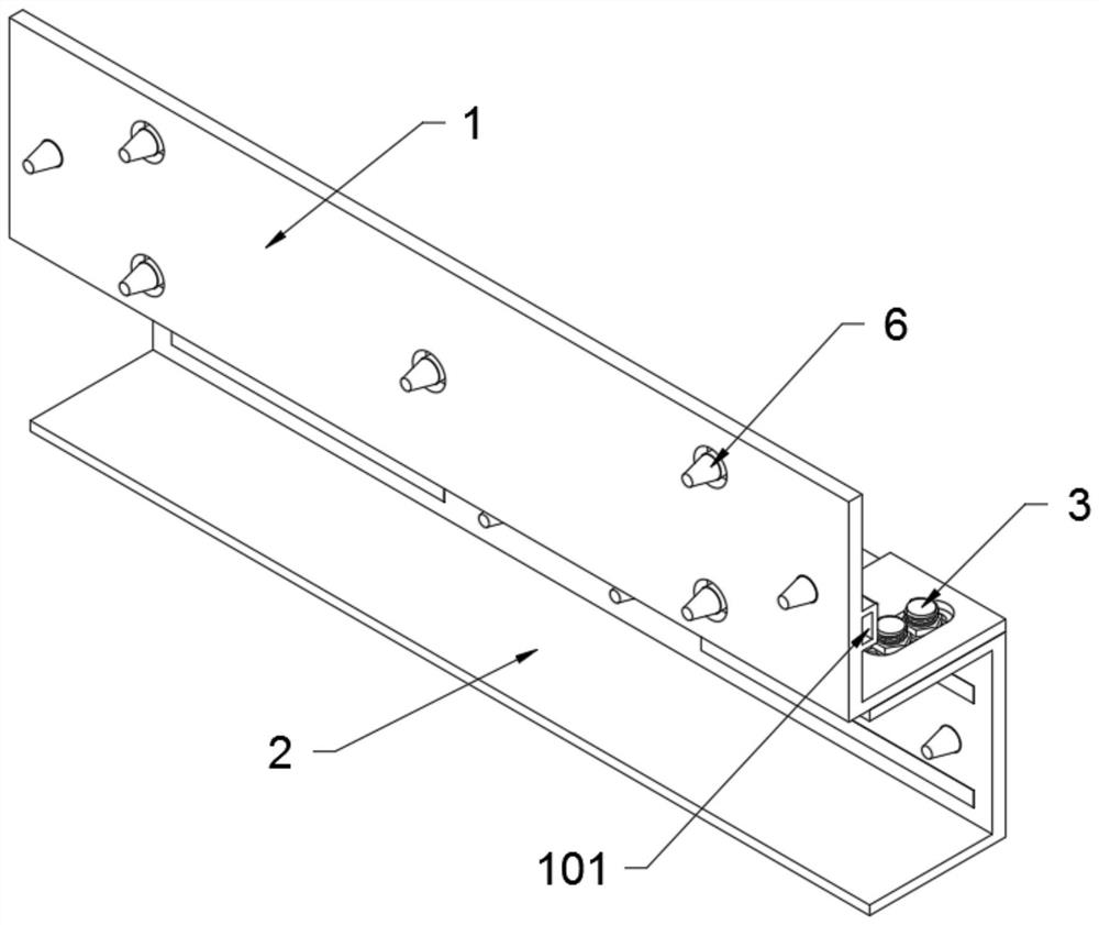
[0033] The present invention provides a door lock support structure, including an L-shaped support frame 1, a buckle groove 101, a door frame connection hole 102, a right-angle force plate 103, an adjustment sliding hole 104, a U-shaped fixing frame 2, a magnetic lock connection hole 201, Positioning holes 202, positioning bolts 3, magnetic strips 4, housing 5, blocks 501, wire connection holes 502 and screws 6; the top of the L-shaped support frame 1 is provided with a plurality of door frame connection holes 102, and the L-shaped support frame 1 The internal screw 6 is installed on the inside of the top of the door frame through the door frame connection hole 102; the right angle force plate 103 is located in the top of the L-shaped support frame 1; the bottom of the L-shaped support frame 1 is provided with three adjustment slide holes 104, and the positioning bolt 3 The top is slidingly connected in the adjustment ...


PUM


Abstract

The invention provides a door lock bracket structure, including wire connection holes and screws; the top of the L-shaped support frame is provided with a plurality of door frame connection holes, and the L-shaped support frame is installed on the inner side of the top of the door frame through the internal screws of the door frame connection holes; There are three adjustment sliding holes at the bottom of the L-shaped support frame, and the top of the positioning bolt is slidably connected in the adjustment sliding holes; the magnetic lock is installed inside the U-shaped fixing frame, and there are multiple The magnetic lock connection hole is located, and the magnetic lock is fixedly connected to the inside of the U-shaped bracket through the internal screws of the magnetic lock connection hole; it is beneficial to increase the force effect on the bottom of the L-shaped support frame, and avoid excessive tension on the bottom of the L-shaped support frame, resulting in The bottom of the L-shaped support frame is bent and deformed, which affects the contact effect between the magnetic lock and the iron sheet; and with the use of the shell and the clamping block, the bracket can be wrapped and fixed, making the outside of the bracket more concise and beautiful, and convenient for personnel to use.

Description

technical field [0001] The invention belongs to the technical field of door lock brackets, and more specifically relates to a door lock bracket structure. Background technique [0002] The design of the magnetic lock is the same as that of the electromagnet, which uses the principle of electromagnetism. When the current passes through the silicon steel sheet, the electromagnetic lock will generate a strong suction force and tightly absorb the adsorption iron plate to achieve the effect of locking the door. The installation of the magnetic lock requires a special bracket to fix the magnetic lock itself so that the personnel can lock the door and use it. [0003] The inventors have found that there are similar door lock brackets, such as the MD190 cabinet door lock bracket mentioned in patent application number CN201320168813. The board, the rear side board and the right side board are integrally formed, wherein the rear side board is provided with a mounting hole and has a b...

Claims


Application Information

Patent Timeline
Patent Type & Authority Patents(China)
IPC IPC(8): E05B17/00E05B47/00
Inventor 张作利
Owner 张作利
Learn More