Turbine condenser vacuum-pumping system with coolers and control method

A technology of vacuum pumping system and cooling device

Inactive Publication Date: 2019-05-03
SHAANXI WEIHE POWER GENERATION CO LTD +1
View PDF6 Cites 1 Cited by
  • Summary
  • Abstract
  • Description
  • Claims
  • Application Information

AI Technical Summary

Problems solved by technology

[0003] In actual operation, when the high back pressure pumping heat supply is running in summer, due to the increase of ambient temperature, the vacuum pump is used to pump air to reduce the air partial pressure and increase the vacuum. The vacuum pump will not only suck more water vapor into the The vacuum pump causes cavitation, damages the equipment, and shortens the service life of the pump. Moreover, the actual working temperature of the vacuum pump (>20°C) is generally higher than the design working temperature (15°C) of the vacuum pump. The working temperature will greatly reduce the suction capacity of the vacuum pump of the existing unit, which will affect the safety and economy of the unit

Method used


Image

  • Turbine condenser vacuum-pumping system with coolers and control method
  • Turbine condenser vacuum-pumping system with coolers and control method
  • Turbine condenser vacuum-pumping system with coolers and control method

Examples


Embodiment Construction

[0030] The present invention will be further described in detail below in conjunction with specific embodiments, which are explanations of the present invention rather than limitations.

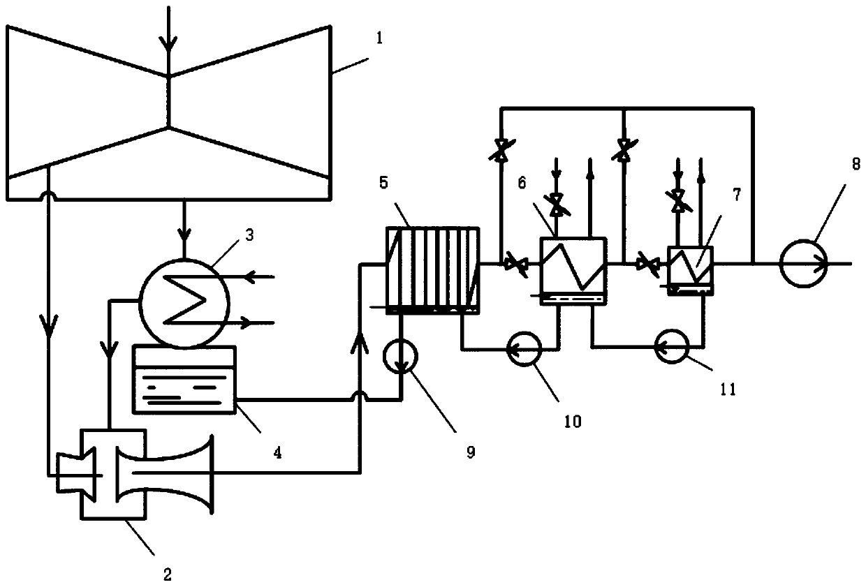
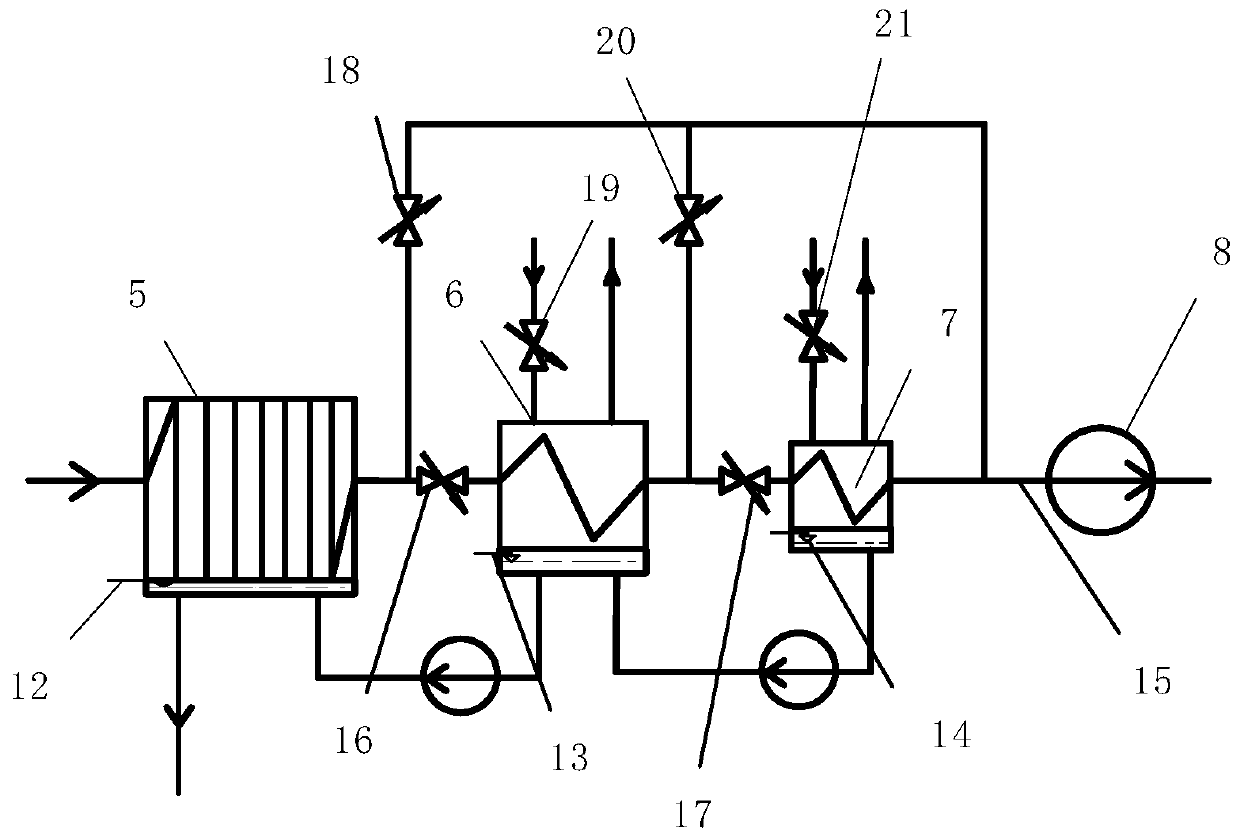
[0031] A vacuum pumping system for a steam turbine condenser with a cooling device of the present invention includes a vacuum pump 8 and three sequentially connected cooling devices, specifically an air cooler 5, a cooling water cooler 6 and a chilled water cooler 7; and a steam turbine 1. Steam jet extractor 2, condenser 3, hot well 4, and pipelines connecting each component; the second-end high-temperature and high-pressure exhaust outlet of the steam turbine 1 passes through the pipeline and the jet port of steam jet extractor 2 Connect, the exhaust steam outlet of steam turbine 1 is connected with the inlet of condenser 3 through pipeline; The outlet of described condenser 3 is connected with the inlet of steam ejector 2 through pipeline, and it is also connected hot well 4; The working s...


PUM


Abstract

The invention relates to a power generation assisting device, in particular to a turbine condenser vacuum-pumping system with coolers and a control method. Waste steam of a turbine is stored in a hotwell after being condensed in a condenser; non-condensable gas is introduced to a gas inlet of a steam-jet ejector; and exhaust air at the penultimate stage of the turbine is introduced to a jet portof the steam-jet ejector. The system comprises the air cooler, the cooling water cooler, the freezing water cooler and a vacuum pump which are sequentially connected to an air outlet of the steam-jetejector, wherein an air outlet of the air cooler is connected with an air inlet of the cooling water cooler through a first valve; an air outlet of the cooling water cooler is connected with an air inlet of the freezing water cooler through a second valve; the air outlet of the air cooler is connected with the vacuum pump through a first bypass with a third valve; and the air outlet of the coolingwater cooler is connected with the vacuum pump through a second bypass with a fourth valve.

Description

technical field [0001] The invention relates to an auxiliary equipment for power generation, in particular to a vacuum pumping system and a control method for a steam turbine condenser with a cooling device. Background technique [0002] The condenser is one of the important auxiliary equipment of the power plant. The vacuum degree of the condenser is directly related to the power generation efficiency, which in turn affects the efficiency of the power plant. The non-condensable gas that enters the condenser with other factors is suctioned and discharged into the air. [0003] In actual operation, when the high back pressure pumping heat supply is running in summer, due to the increase of ambient temperature, the vacuum pump is used to pump air to reduce the air partial pressure and increase the vacuum. The vacuum pump will not only suck more water vapor into the The vacuum pump causes cavitation, damages the equipment, and shortens the service life of the pump, and the act...

Claims


Application Information

Patent Timeline
Patent Type & Authority Applications(China)
IPC IPC(8): F28B9/10F28B11/00
Inventor 黄卫东宋宏林卢旭超谭厚章
Owner SHAANXI WEIHE POWER GENERATION CO LTD
Why Eureka
Try Eureka