
A bedrock buried hill crack prediction method and device

A fracture prediction and bedrock technology, applied in the field of petroleum exploration, can solve the problems of decreased accuracy, inability to predict the whole area, and limited amount of data

Active Publication Date: 2019-05-03
PETROCHINA CO LTD
View PDF3 Cites 22 Cited by
  • Summary
  • Abstract
  • Description
  • Claims
  • Application Information

AI Technical Summary

Problems solved by technology

[0003] In the existing technology for the identification and prediction of fractures in granite bedrock buried hill reservoirs, although some technical methods for fracture identification and modeling have been formed, all methods have their adaptability
In addition, due to the absorption and attenuation of seismic wave energy by granite / metamorphic rocks, the seismic quality inside the buried hill is poor and the accuracy is reduced
Relying on core, thin section data and imaging logging for description, the identification accuracy is high, but due to the high cost, the amount of data available for analysis is limited, and the whole area cannot be well predicted
Moreover, compared with traditional sedimentary fractured reservoirs, granite / metamorphic bedrock buried hills have more types of rocks, stronger reservoir heterogeneity, and the influence of structure and weathering and leaching, so that fractures develop vertically and laterally There are strong differences, and fracture prediction is more difficult, and it cannot be fully characterized by traditional sedimentary rock modeling methods

Method used


Image

  • A bedrock buried hill crack prediction method and device
  • A bedrock buried hill crack prediction method and device
  • A bedrock buried hill crack prediction method and device

Examples


Embodiment Construction

[0055]The following will clearly and completely describe the technical solutions in the embodiments of the present invention with reference to the accompanying drawings in the embodiments of the present invention. Obviously, the described embodiments are only some, not all, embodiments of the present invention. Based on the embodiments of the present invention, all other embodiments obtained by persons of ordinary skill in the art without making creative efforts belong to the protection scope of the present invention.

[0056] Although some technical methods for fracture identification and modeling have been formed, each method has its adaptability. Due to the absorption and attenuation of seismic wave energy by granite / metamorphic rocks, the seismic quality of the inner buried hill is poor and the accuracy is reduced. Relying on core, thin-section data and imaging logging for description has high identification accuracy, but due to the high cost, the amount of data available ...


PUM


Abstract

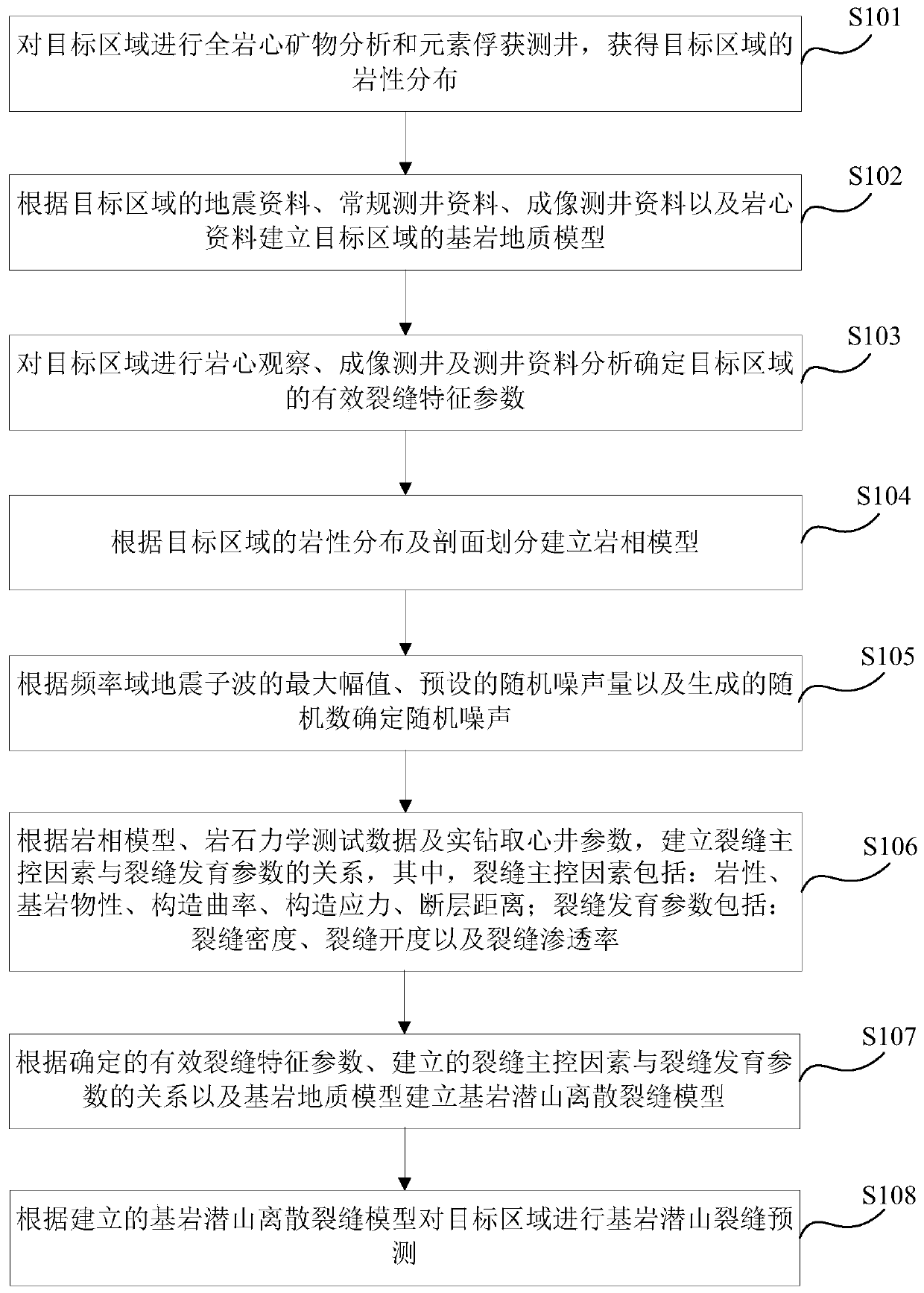
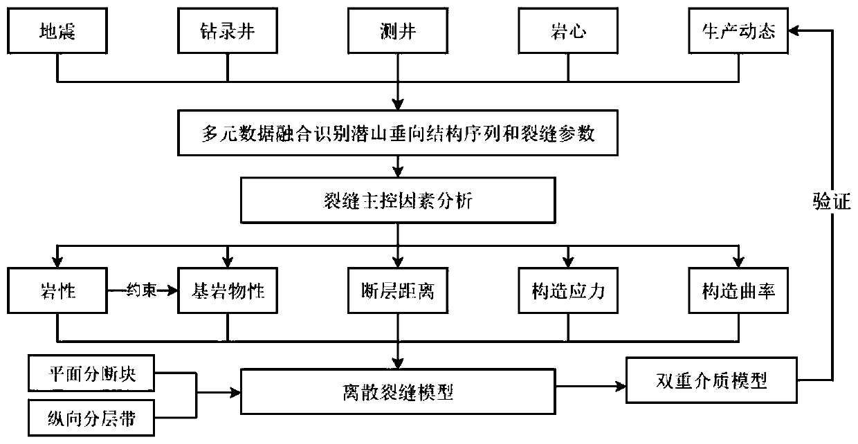
The invention provides a bedrock buried hill crack prediction method and device, and the method comprises the steps: carrying out the full-core mineral analysis and element capture logging of a targetregion, and obtaining the lithology distribution; establishing a bedrock geological model according to the seismic data, the conventional logging data, the imaging logging data and the core data of the target area; performing rock core observation, imaging logging and logging data analysis to determine effective crack characteristic parameters of the target area; performing a rock mechanics testto generate rock mechanics test data; establishing a relationship between the crack main control factors and the crack development parameters; and establishing a bedrock buried hill discrete fracturemodel according to the determined effective fracture characteristic parameters, the established relationship between the fracture main control factors and the fracture development parameters and the bedrock geological model, and performing bedrock buried hill fracture prediction on the target area. By integrating multi-source data and various methods, the crack development of the buried hill bedrock reservoir is identified and predicted, finally, a discrete crack model is established, and exploration and development of the buried hill bedrock reservoir are guided.

Description

technical field [0001] The invention relates to oil exploration technology, in particular to a method and device for predicting cracks in bedrock buried hills. Background technique [0002] Bedrock buried hills are metamorphic or igneous rock combinations below the sedimentary sequence, and bedrock buried hills contain sedimentary rocks with very low porosity or no matrix pores. Buried hill oil reservoirs are often discovered when deep drilling shallow clastic rock reservoirs, and usually have high single well production, which is of great significance in oil exploration and development. [0003] In the prior art, in the identification and prediction of fractures in granite bedrock buried hill reservoirs, although some technical methods for fracture identification and modeling have been formed, all methods have their adaptability. In addition, due to the absorption and attenuation of seismic wave energy by granite / metamorphic rocks, the seismic quality inside the buried hil...

Claims


Application Information

Patent Timeline
IPC IPC(8): G06F17/50G01N33/24
Inventor 晋剑利李贤兵孙致学张瑾琳李香玲姜传胤徐锋郑学锐肖康
Owner PETROCHINA CO LTD
Learn More