
RFID read-write antenna design method for LCD screen

A technology for reading and writing antennas and design methods, which is applied to antennas, loop antennas, and record carriers used by machines. It can solve the problems of large terminal equipment and limit the size of LCD screens of vehicle-mounted consumer terminals, and achieve volume saving and expansion of use area. Effect

Pending Publication Date: 2019-05-03
天津渤海化学股份有限公司
View PDF6 Cites 0 Cited by
  • Summary
  • Abstract
  • Description
  • Claims
  • Application Information

AI Technical Summary

Problems solved by technology

At present, all of these vehicle-mounted consumer terminals do not overlap the RFID radio frequency area and the display area, which limits the size of the LCD screen used by the vehicle-mounted consumer terminal, making the terminal device have a larger volume

Method used


Image

  • RFID read-write antenna design method for LCD screen
  • RFID read-write antenna design method for LCD screen
  • RFID read-write antenna design method for LCD screen

Examples


Embodiment Construction

[0027] It should be noted that, in the case of no conflict, the embodiments of the present invention and the features in the embodiments can be combined with each other.

[0028] In describing the present invention, it should be understood that the terms "center", "longitudinal", "transverse", "upper", "lower", "front", "rear", "left", "right", " The orientations or positional relationships indicated by "vertical", "horizontal", "top", "bottom", "inner" and "outer" are based on the orientations or positional relationships shown in the drawings, and are only for the convenience of describing the present invention and Simplified descriptions, rather than indicating or implying that the device or element referred to must have a particular orientation, be constructed and operate in a particular orientation, and thus should not be construed as limiting the invention. In addition, the terms "first", "second", etc. are used for descriptive purposes only, and should not be understood ...


PUM


Abstract

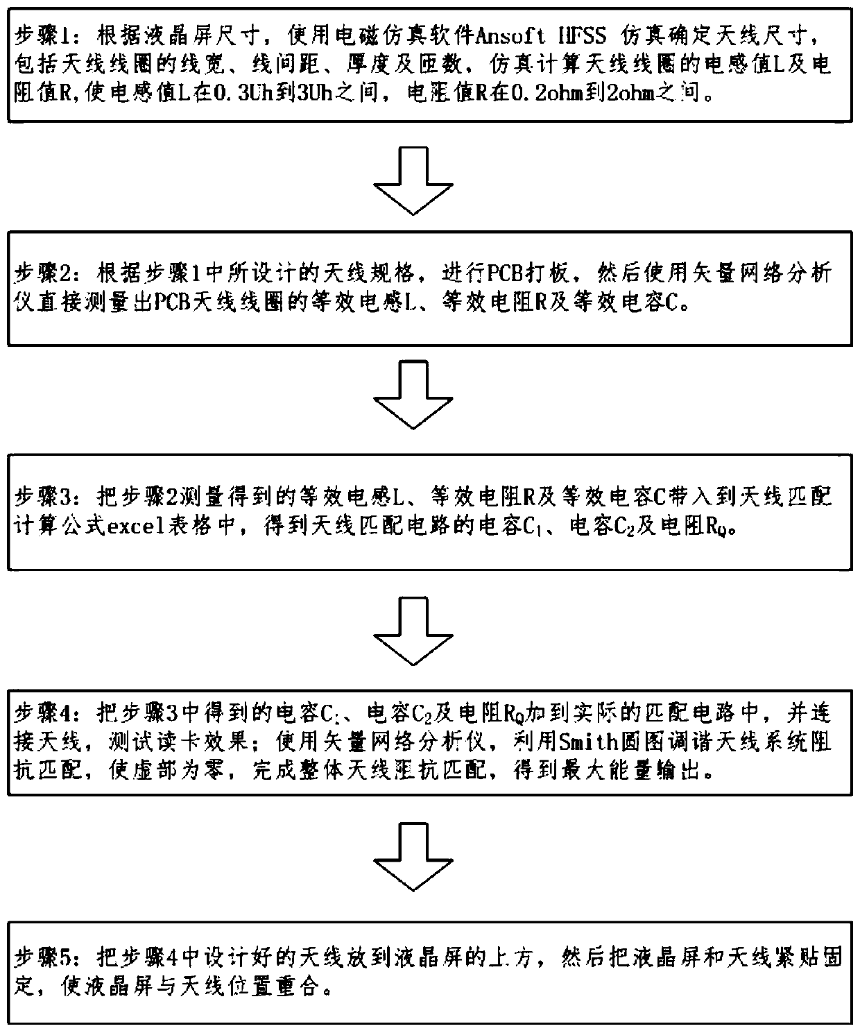
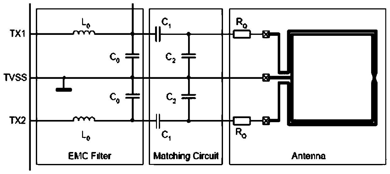
The invention provides an RFID read-write antenna design method for an LCD screen, and the method comprises the following steps: performing simulation through electromagnetic simulation software Ansoft HFSS according to the size of the LCD screen to determine the size of an antenna; performing PCB sample proofing, and then directly measuring an equivalent inductance L, an equivalent resistance R and an equivalent capacitance C of a PCB antenna coil by using a vector network analyzer; substituting the parameters into an excel table of an antenna matching calculation formula to obtain a capacitance C1, a capacitance C2 and a resistance RQ of an antenna matching circuit. The invention relates to the RFID read-write antenna design method for the LCD screen, so that an RFID radio frequency areaand an LCD screen display area are overlapped, the limitation that a traditional card swiping area and a traditional display area cannot be the same area is broken through, the display area is the card swiping area, the use area of the vehicle-mounted consumption terminal is expanded, and the size of vehicle-mounted equipment is greatly saved.

Description

technical field [0001] The invention belongs to the field of non-contact payment for urban public transport, and in particular relates to a design method for an RFID read-write antenna used for LCD liquid crystal screens. Background technique [0002] A complete RFID system generally includes a reader and an electronic tag. There are two ways to couple the RF signal between the two. Electromagnetism Opposite Direction Dispersion coupling (Electromagnetism Opposite Direction Dispersion coupling) and Inductance coupling (Inductance coupling), the electromagnetic backscatter coupling method is generally applicable to 433MHz, 841MHz, 915MHz, 2.45GHz, 5.8GHz and other high frequency, ultra high frequency and microwave frequency bands In the long-distance RFID system that works, its recognition range is usually greater than 1m, and the typical range is 3m to 10m. Inductive coupling is the transmission of energy and signals between coils through a high-frequency alternating magne...

Claims


Application Information

Patent Timeline
IPC IPC(8): H01Q7/00H01Q1/22H04B5/00G06K19/077
Inventor 朱万山刘兴刚杨庆伯左志坚仝连云
Owner 天津渤海化学股份有限公司
Learn More