Automatic dehumidification power transformation box

A transformer box, automatic technology, applied in the field of transformer box, can solve the problem that the air humidity of the transformer box cannot be changed automatically, and achieve the effect of prolonging the temperature rise time, increasing the sensitivity, and being convenient to use

Active Publication Date: 2019-05-03
源洲电气有限公司
View PDF9 Cites 6 Cited by
  • Summary
  • Abstract
  • Description
  • Claims
  • Application Information

AI Technical Summary

Problems solved by technology

[0003] An automatic dehumidification transformer box is set to solve the problem that the air humidity inside the transformer box cannot be automatically changed in the above-mentioned background technology

Method used


Image

  • Automatic dehumidification power transformation box
  • Automatic dehumidification power transformation box
  • Automatic dehumidification power transformation box

Examples


Embodiment Construction

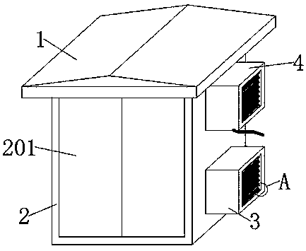
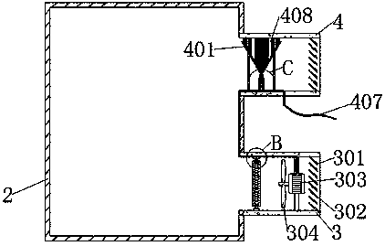
[0032] see Figures 1 to 11Among them, in the embodiment of the present invention, an automatic dehumidification transformer box includes a top plate 1, a dehumidification cylinder 3, a control cylinder 4 and a box body 2. The top plate 1 is welded on the top of the box body 2, and the right side of the box body 2 is embedded The dehumidification cylinder 3 and the control cylinder 4 are welded, and the dehumidification cylinder 3 is located directly above the control cylinder 4, and the front surface of the box body 2 is hinged with two cabinet doors 201; the dehumidification cylinder 3 includes an inclined plate 301, a vertical plate 302, Electric motor 303, fan blade 304, insulating seat 305, heat insulation rod 306, heat insulation conductive rod 307 and electric heating pipe 308, the right side of the inner wall of dehumidification cylinder 3 and the right side of the inner wall of control cylinder 4 are all welded with eight inclined plates 301 The right side of the top ...


PUM


Abstract

The invention provides an automatic dehumidification power transformation box, which comprises a top plate, a dehumidification cylinder, a control cylinder and a box body. The top plate is welded to the top of the box body. The dehumidification cylinder and the control cylinder are welded to the right side of the box body in an embedded mode. The dehumidification cylinder is located right over thecontrol cylinder. Two cabinet doors are hinged to the front surface of the box body through hinges. According to the invention, when the air humidity in the box body is increased, the heat of the aqueous vapor can be quickly absorbed by metal water collecting barrels when the aqueous vapor gets in contact with the metal water collecting barrel. Therefore, the aqueous vapor in the metal water collecting barrels can be quickly liquefied on the inner wall of the metal water collecting barrels to form water drops. After the water drops are accumulated to a certain extent, the water drops flow down along the inner wall of the metal water collecting barrel and flow towards water running plates. When water on the water running plates comes up together, the two water running plates can form a current loop. In this way, a power supply for a motor and an electric heating pipe is switched on by an electric wire. The electric heating pipe starts heating to dry the air. The motor drives fan bladesto rotate to form the airflow and the airflow is driven to blow into the box body. The air humidity in the box body is reduced, and the automatic dehumidification is achieved.

Description

technical field [0001] The invention relates to the technical field of transformer boxes, in particular to an automatic dehumidification transformer box. Background technique [0002] A transformer box is a box in a power system where the voltage and current of electric energy are transformed, concentrated and distributed. In order to ensure the quality of electric energy and the safety of equipment, voltage adjustment, power flow control, and protection of transmission and distribution lines and main electrical equipment are required in the transformer box. It is mainly used to protect the boxes of power facilities. At present, many transformer boxes are It is installed outdoors. When the substation box encounters heavy rain, the air humidity in the substation box will increase, and the insulation capacity of the air in the substation box will decrease. The air humidity in the electric box increases, and the operation of the power facilities becomes unstable, and the exist...

Claims


Application Information

Patent Timeline
Patent Type & Authority Applications(China)
IPC IPC(8): H02B1/46H02B1/28H02B1/56
Inventor 陆文法
Owner 源洲电气有限公司
Why Eureka
Try Eureka