
A layout method for energy saving of factory lighting

A technology for factory lighting and factory areas, applied in lighting devices, light sources, electrical components, etc., can solve problems such as difficult compatibility, lamps and appliances scrapped, and low recycling value, so as to reduce material and labor costs, improve efficiency, and realize The effect of overall voltage reduction and energy saving

Active Publication Date: 2020-06-26
SHANGHAI MUNICIPAL ELECTRIC POWER CO +3
View PDF6 Cites 0 Cited by
  • Summary
  • Abstract
  • Description
  • Claims
  • Application Information

AI Technical Summary

Problems solved by technology

[0002] Lighting energy saving is the simplest and most feasible energy-saving means for industrial and mining enterprises to implement energy-saving transformation. However, the existing technology also requires a large amount of initial investment in lighting energy saving, such as replacing lamps and replacing LED light sources. This aspect requires a large initial cost. On the other hand, a large number of lamps and appliances whose service life has not yet expired are scrapped ahead of time, which saves energy but wastes resources.
Traditional lighting equipment generally contains a large amount of harmful metal elements such as lead and mercury. Lamp products generally have little recycling value, and existing LED lighting equipment is difficult to be compatible with traditional lamps. This makes many harmful existing Lamp components pollute the environment because they cannot be effectively recycled. For this problem, if there is technology to fully tap the energy-saving potential of existing lamps and reduce energy consumption on the basis of making full use of existing lamps, it will not only It can effectively overcome the potential environmental pollution hazards caused by discarding existing lamps, and can also greatly reduce the cost of renovation. This can obviously greatly enhance the enthusiasm of enterprises for energy-saving renovation, while reducing resource waste, and achieving dual intensive use of energy and resources. And it coincides with the concept of circular economy and sustainable development currently advocated

Method used


Image

  • A layout method for energy saving of factory lighting
  • A layout method for energy saving of factory lighting

Examples


Embodiment Construction

[0024] The present invention will be described in detail below in conjunction with the accompanying drawings and specific embodiments. Apparently, the described embodiments are some, not all, embodiments of the present invention. Based on the embodiments of the present invention, all other embodiments obtained by persons of ordinary skill in the art without making creative efforts shall fall within the protection scope of the present invention.

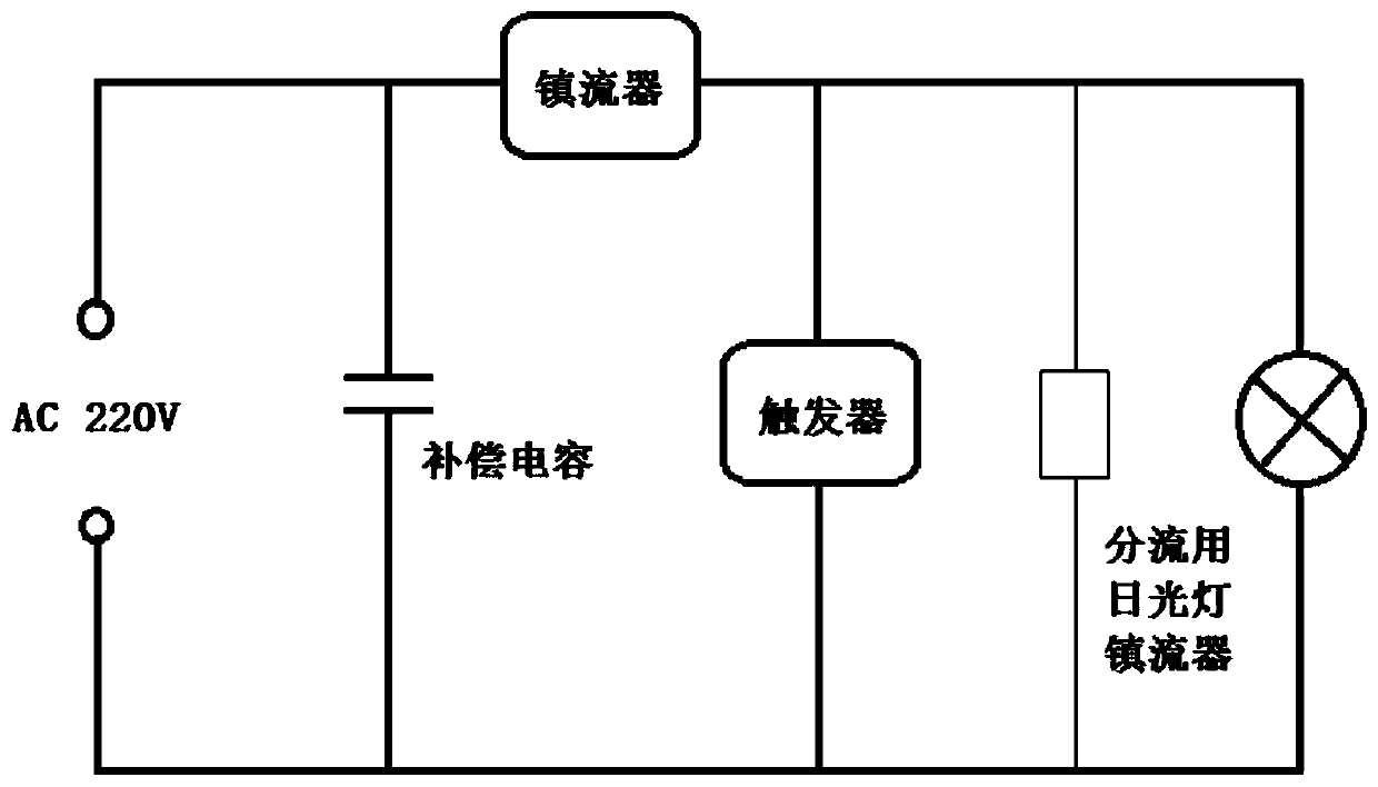
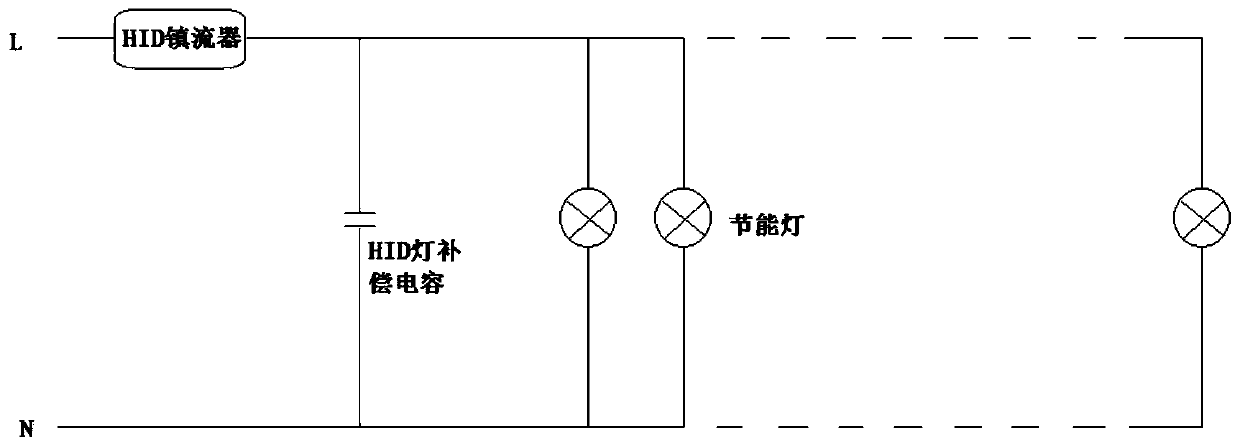
[0025] The technical solution of the embodiment of the present invention is: firstly, the mature nano-reflective technology is used to fully exploit the efficiency of the existing lamps. The traditional lighting source has a 360° full-scale light emission. Reflected back, however, the metal reflectors used in ordinary lamps are prone to rapid aging due to the influence of external light, etc., resulting in yellowing and darkening, which greatly reduces the reflection efficiency, which makes the actual efficiency of many existing lamps...


PUM


Abstract

The invention relates to a layout method for illumination energy saving of a factory. According to the method, the efficiency of an existing lamp is improved by a cheap nano light reflecting material,so that a part of lamps or light sources are stopped; a ballast is utilized to realize current limiting and energy saving of other illumination loops, so the illumination equipment of the whole factory is recycled, and the purposes of high efficiency and energy saving are realized under the condition that the light sources are not replaced. Compared with the prior art, the method has the advantages that 30-40% of the comprehensive energy-saving efficiency can be realized under the condition that the input is basically zero; and remarkable economic benefits and social benefits can be brought along with the successful application of the project.

Description

technical field [0001] The invention relates to an energy-saving method, in particular to a layout method for factory lighting energy-saving. Background technique [0002] Lighting energy saving is the simplest and most feasible energy-saving means for industrial and mining enterprises to implement energy-saving transformation. However, the existing technology also requires a large amount of initial investment in lighting energy saving, such as replacing lamps and replacing LED light sources. This aspect requires a large initial cost. On the other hand, a large number of lamps and appliances whose service life has not yet arrived are scrapped ahead of time, which saves energy but wastes resources. Traditional lighting equipment generally contains a large amount of harmful metal elements such as lead and mercury. Lamp products generally have little recycling value, and existing LED lighting equipment is difficult to be compatible with traditional lamps. This makes many harmfu...

Claims


Application Information

Patent Timeline
Patent Type & Authority Patents(China)
IPC IPC(8): H05B41/14
Inventor 杨欢红洪雨谢锦芳徐中华李世伟余霄骏
Owner SHANGHAI MUNICIPAL ELECTRIC POWER CO
Learn More