Safety charging gun

A charging gun and safety technology, applied in the field of charging guns, can solve problems such as inconvenient use, potential safety hazards, insufficient heat dissipation, etc., and achieve the effects of protecting personal safety, good heat dissipation performance, and a good sense of experience

Active Publication Date: 2019-05-07
东莞市东南新能源科技有限公司
12 Cites 2 Cited by

AI-Extracted Technical Summary

Problems solved by technology

For the automobile industry, people use electric vehicles as a new means of transportation, and the charging of electric vehicles has always been the key to the use of electric vehicles. Generally speaking, during the charging process, due to the insufficient heat dissipation capacity of the existing charg...

Method used

In order to better dissipate heat to the heat dissipation block 6 and the power terminal 3, utilize the filled heat-conducting material 40 to carry out contact heat dissipation, and the heat-conducting material 40 is injected from the injection hole 41 , it is convenient and quick to make, and the effect is good.
[0032] The heat dissipation block 6 further dissipates heat on the outer surface of the groove 30 and the outer surface of the protruding strip 29, because compared to the cylindrical ...

Abstract

The invention discloses a safety charging gun. The safety charging gun comprises a first housing, a second housing, a power terminal, a signal terminal, an earth wire terminal, a heat radiation block,a signal bracket, an earth wire peak, a terminal plug, a fixing block, an air guide safety cover, an air guide groove, a heat radiation fan, a conductive rubber block and a heat sensor; the air guidesafety cover is arranged on the external side of the heat radiation block in a sleeving manner; a groove and a convex strip are arranged on the external side of the heat radiation block; an air guidehole is formed in the fixing block; a mounting groove is formed in the heat radiation block; the heat sensor is positioned in the mounting groove; the heat radiator is electrically connected with theheat radiation fan; the earth wire terminal runs through the conductive rubber block; the conductive rubber block is connected with the heat radiation block; an injection hole is formed in the heat radiation block; and the groove and the injection hole are filled with heat conducting materials. According to the safety charging gun, the heat radiation fan can be controlled to blow air into the charging gun to radiate heat in real time; and moreover, the heat radiation performance of the charging gun is good, an electric leakage preventing function is realized, the personal safety is effectively protected, the structure is compact, the use is convenient, and the experience feeling of a user is good.

Application Domain

Technology Topic

Image

  • Safety charging gun
  • Safety charging gun
  • Safety charging gun

Examples

  • Experimental program(1)

Example Embodiment

[0027] The technical solutions of the present invention will be further described below in conjunction with the drawings and specific implementations.
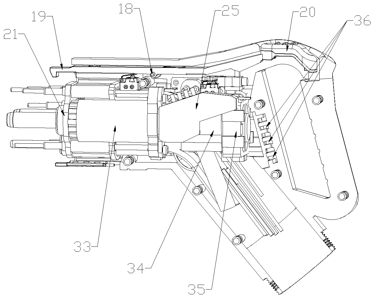
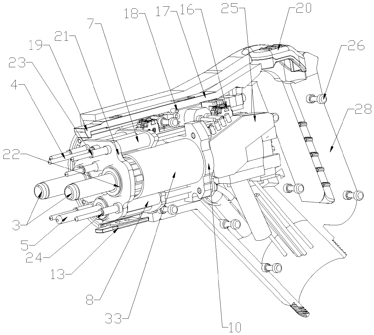
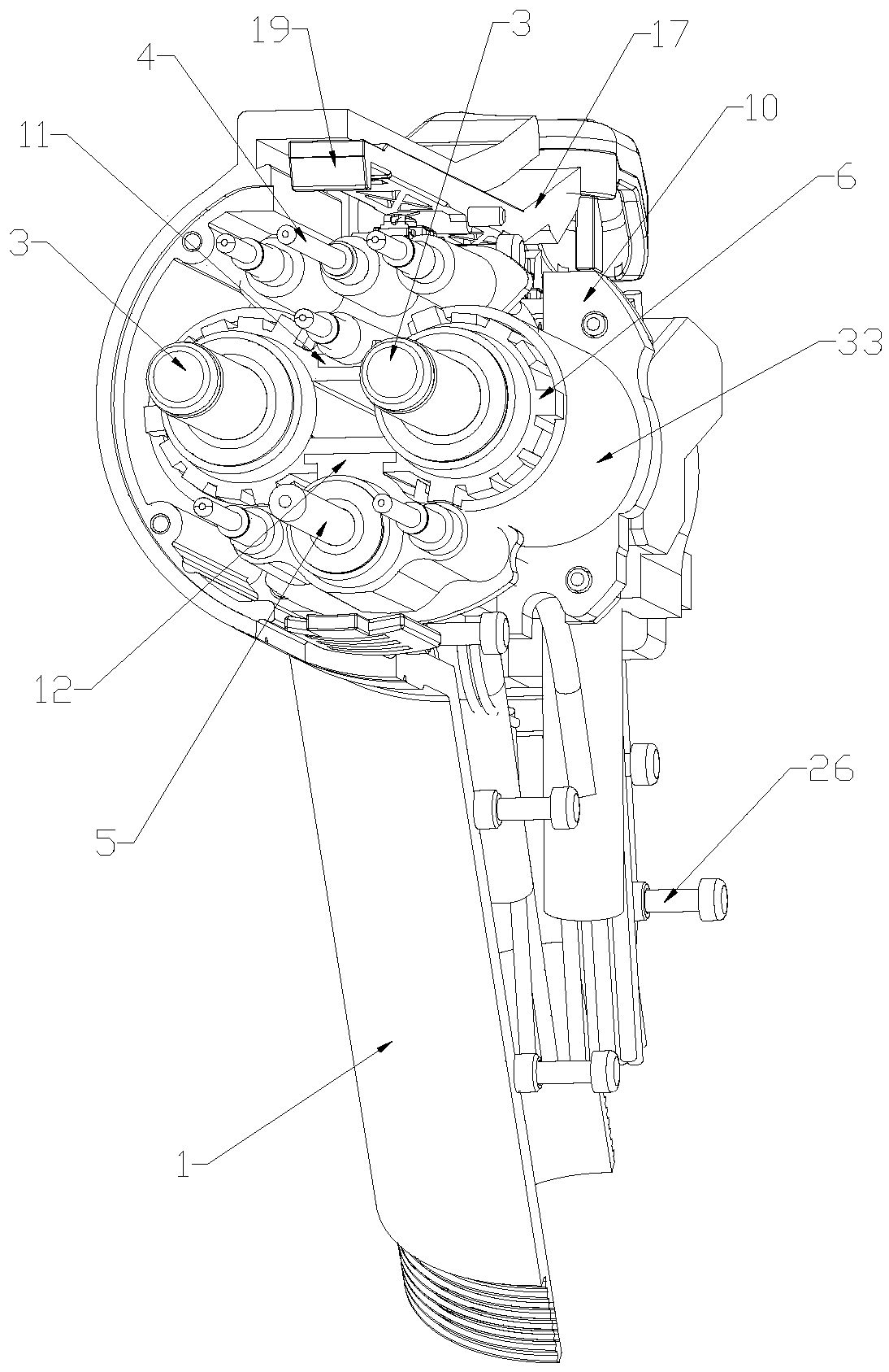
[0028] Such as Figure 1 to Figure 9 As shown, in this embodiment, a safety charging gun includes a first housing 1, a second housing 2, a power terminal 3, a signal terminal 4, a ground terminal 5, a heat sink 6, a signal support 7, and a ground support 8. Terminal plug 9, fixed block 10, air guide safety cover 33, air guide groove 34, heat dissipation fan 35, conductive rubber block 39 and thermal sensor 38, said power terminal 3 penetrates said heat dissipation block 6, said signal terminal 4 penetrates the signal support 7, the ground terminal 5 penetrates the ground support 8, the signal support 7, the ground support 8 and the heat sink 6 are all located inside the terminal plug 9, The signal terminal 4, the ground terminal 5 and the power terminal 3 all pass through the terminal plug 9, and the terminal plug 9 and the fixing block 10 are all located in the first housing 1 and the second housing 1 Between the housings 2, the terminal plug 9 is fixedly connected to the fixing block 10, the air guide safety cover 33 is sleeved on the outside of the heat dissipation block 6, and the outside of the heat dissipation block 6 is provided with a number of grooves 30 And a number of protruding strips 29, one end of the air guide groove 34 is fixedly connected to the side of the fixing block 10 away from the terminal plug 9, and the other end of the air guide groove 34 is connected to the heat dissipation fan 35, so The fixing block 10 is provided with air guide holes, the heat dissipation block 6 is provided with a mounting slot, the thermal sensor 38 is located in the mounting slot, the thermal sensor 38 is electrically connected to the heat dissipation fan 35, so The ground wire bracket 8 is provided with a mounting groove at one end away from the terminal plug 9, the conductive rubber block 39 is located in the mounting groove, the ground terminal 5 penetrates the conductive rubber block 39, the conductive rubber block 39 is connected to the heat dissipation block 6. The heat dissipation block 6 is provided with an injection hole 41 penetrating the outer surface of the heat dissipation block 6 and the inner surface of the heat dissipation block 6, the groove 30 and the injection hole 41 41 are filled with a thermally conductive material 40.
[0029] When the electric vehicle needs to be charged, the terminal plug 9 is inserted into the electric vehicle, the signal terminal 4 is responsible for receiving and releasing the charging signal, and the ground terminal 5 is responsible for providing safety protection and preventing electric shocks. The power terminal 3 needs to transmit electric energy to the electric vehicle. The power terminal 3 is easy to generate heat during the charging process, and the heat is absorbed by the heat sink 6.
[0030] The terminal plug 9 is provided with a movable groove 14, and an exhaust plate 13 is slidably connected to the movable groove 14, a first exhaust port is provided on the exhaust plate 13, and the groove wall of the movable groove 14 A second air exhaust port 15 is provided, and the air exhaust plate 13 is manually pushed, and when the first air exhaust port and the second air exhaust port 15 are in communication, the higher temperature gas is exhausted to the outside.
[0031] Specifically, the groove 30 and the protruding strip 29 are spaced apart, and the length direction of the groove 30 and the length direction of the protruding strip 29 are both consistent with the length direction of the power terminal 3.
[0032] The heat dissipating block 6 further dissipates heat on the outer surface of the groove 30 and the outer surface of the protruding bar 29. As compared with the cylindrical heat dissipating block 6, the groove 30 and the convex After the bars 29 are arranged at intervals, a hollow structure is formed, the contact area with the air is larger, and the hollow structure has a stronger heat dissipation capacity.
[0033] When the temperature of the heat dissipating block 6 reaches a limited temperature, the thermal sensor 38 is triggered, and the thermal sensor 38 controls the heat dissipating fan 35 to start. After the heat dissipating fan 35 starts, the air blows through the air guide groove 34 and The air guide hole enters the gap between the air guide safety cover 33 and the heat dissipation block 6 to blow away the heat of the heat dissipation block 6.
[0034] When the power terminal 3 accidentally leaks, the leakage current is introduced into the ground terminal 5 by the conductive rubber block 39 through the contact with the heat dissipation block 6, thereby effectively protecting the safety charging gun from Leakage, safe and reliable.
[0035] Specifically, the thermally conductive material 40 is heat-dissipating silicone grease, and in other embodiments, the thermally conductive material 40 may also be graphene, thermally conductive silicone, thermally conductive paste, heat-dissipating paste, and the like.
[0036] In order to better dissipate the heat of the heat dissipation block 6 and the power terminal 3, the filled thermal conductive material 40 is used for contact heat dissipation, and the thermal conductive material 40 is injected from the injection hole 41, which is convenient to manufacture Fast and effective.
[0037] Preferably, the length of the power terminal 3 is 70 mm.
[0038] Compared with the current power terminal 3 with a length of 40 mm to 45 mm, the power terminal 3 with a length increased to 70 mm can increase the heat dissipation area, and conduct heat through the heat sink 6 as much as possible in the length direction To the outside of the charging gun.
[0039] In this embodiment, the first housing 1 is provided with a first ventilation hole 36 and the second housing 2 is provided with a second ventilation hole.
[0040] The first vent hole 36 and the second vent hole form the air inlet of the heat dissipation fan 35, and supply air to the inside of the overall structure.
[0041] In this embodiment, the upper end of the heat dissipation block 6 is provided with a first slide groove 31, and the lower end of the signal bracket 7 is provided with a first slide rail 11, and the first slide groove 31 is connected to the first slide rail. 11 Sliding connection, the lower end of the heat sink 6 is provided with a second slide groove 32, the upper end of the ground wire bracket 8 is provided with a second slide rail 12, the second slide groove 32 and the second slide rail 12 Sliding connection.
[0042] During installation, the signal bracket 7 can be connected to the heat dissipation block 6 through the first sliding groove 31 and the first sliding rail 11, and the second sliding groove 32 is connected to the second sliding rail 11. The rail 12 can connect the ground wire bracket 8 and the heat dissipation block 6 to fix the relative positions of the power terminal 3, the signal terminal 4 and the ground wire terminal 5, which is suitable for electric vehicles. The charging interface on the upper side performs charging, and the signal bracket 7, the ground wire bracket 8 and the heat dissipation block 6 are integrated, and the overall heat dissipation performance is good.
[0043] In this embodiment, it includes an electronic lock 16, a lock bar 17 and a lock shaft 18. Both ends of the lock shaft 18 are connected to the first housing 1 and the second housing 2, respectively. The electronic lock 16 is fixed on the fixing block 10, the locking shaft 18 penetrates the middle of the locking bar 17, and the locking bar 17 is provided with a locking hook 19 at one end close to the terminal plug 9.
[0044] When charging, when the terminal plug 9 is inserted into the electric vehicle, the lock hook 19 is hooked on the electric vehicle, so that the entire charging gun is fixed to the electric vehicle, which is convenient for charging; and after the charging is completed, manually press the The locking bar 17 is far away from one end of the locking hook 19, and under the action of the locking shaft 18, the locking hook 19 is separated from the electric vehicle, so that the charging gun can be separated from the electric vehicle.
[0045] In this embodiment, a pressing plate 20 is included. The pressing plate 20 is fixed to an end of the locking bar 17 away from the locking hook 19, and the pressing plate 20 is provided with anti-slip patterns.
[0046] The addition of the pressing plate 20 can firstly increase safety and prevent people from getting an electric shock when pressing the locking strip 17, and secondly, the anti-slip pattern on the pressing plate 20 can also enhance the convenience of the structure.
[0047] In this embodiment, a waterproof film 21 is included, the waterproof film 21 is located inside the terminal plug 9, the waterproof film 21 is clamped with the terminal plug 9, the signal terminal 4, the ground terminal Both 5 and the power terminal 3 penetrate the waterproof film 21.
[0048] The waterproof film 21 can prevent the water accidentally entering from the terminal plug 9 from continuing to enter the power terminal 3, the signal terminal 4 or the ground terminal 5, affecting their normal operation, and improving safety To prevent leakage.
[0049] In this embodiment, a first gasket 22, a second gasket 23, and a third gasket 24 are provided between the terminal plug 9 and the waterproof film 21, and the power terminal 3 penetrates the first gasket 22. The signal terminal 4 penetrates the second gasket 23, and the ground terminal 5 penetrates the third gasket 24.
[0050] The first gasket 22, the second gasket 23, and the third gasket 24 are designed so that during the installation process, the power terminal 3 and the terminal plug 9 have good elastic contact, so The signal terminal 4 and the terminal plug 9 have good elastic contact, and the ground terminal 5 and the terminal plug 9 have good elastic contact. All three types of terminals are not easily damaged.
[0051] In this embodiment, a junction box 25 is included. The junction box 25 is fixed on the side of the fixing block 10 away from the terminal plug 9. The signal terminal 4, the ground terminal 5 and the power terminal 3 are electrically connected to the junction box 25.
[0052] The signal wire connected to the signal terminal 4, the ground wire connected to the ground wire terminal 5, and the wire connected to the power terminal 3 are all integrated through the junction box 25.
[0053] In this embodiment, a connecting post is fixed on the side of the first housing 1 close to the second housing 2, the connecting post is provided with a threaded hole, and the second housing 2 is provided with a connecting through hole 27 And a connecting screw 26, the connecting screw 26 passes through the connecting through hole 27 and then is threadedly connected with the threaded hole.
[0054] When the first housing 1 and the second housing 2 wrap the internal components and need to be installed as an integral charging gun, the connecting post plays a guiding role to ensure that the first housing 1 and The second housing 2 is in good contact, the connecting screw 26, the connecting through hole 27 and the threaded hole can fix the first housing 1 and the second housing 2 together, and the overall structure is stable .
[0055] In this embodiment, both the first housing 1 and the second housing 2 are provided with a handle 28.
[0056] The grip 28 is used to grip the whole body during manual charging.
[0057] It needs to be stated that the above-mentioned specific implementations are only the preferred embodiments of the present invention and the technical principles used. Within the technical scope disclosed in the present invention, any changes or substitutions that can be easily thought of by those skilled in the art, All should be covered within the protection scope of the present invention.

PUM

no PUM

Description & Claims & Application Information

We can also present the details of the Description, Claims and Application information to help users get a comprehensive understanding of the technical details of the patent, such as background art, summary of invention, brief description of drawings, description of embodiments, and other original content. On the other hand, users can also determine the specific scope of protection of the technology through the list of claims; as well as understand the changes in the life cycle of the technology with the presentation of the patent timeline. Login to view more.

Similar technology patents

Classification and recommendation of technical efficacy words

  • Good cooling performance
  • Protect personal safety

Remote control director for working dog

Owner:SHENYANG INST OF AUTOMATION - CHINESE ACAD OF SCI
Why Eureka
Try Eureka