Directional vibratory drum capable of switching between rotation and reverse rotation

A vibrating wheel and phase switching technology, applied in roads, road repairs, roads, etc., can solve problems such as single vibration function and complex structure of vibration mechanism

Pending Publication Date: 2019-05-07
黄方权
View PDF4 Cites 3 Cited by
  • Summary
  • Abstract
  • Description
  • Claims
  • Application Information

AI Technical Summary

Problems solved by technology

However, the structure of the existing vibration mechanism is relatively complex, and the vibration function is relatively single, and often can only achieve vertical vibration, so it is urgent to improve

Method used


Image

  • Directional vibratory drum capable of switching between rotation and reverse rotation
  • Directional vibratory drum capable of switching between rotation and reverse rotation
  • Directional vibratory drum capable of switching between rotation and reverse rotation

Examples


Embodiment Construction

[0048] In order to make the object, technical solution and advantages of the present invention clearer, the present invention will be further described in detail below in conjunction with the accompanying drawings. Apparently, the described embodiments are only some of the embodiments of the present invention, but not all of them.

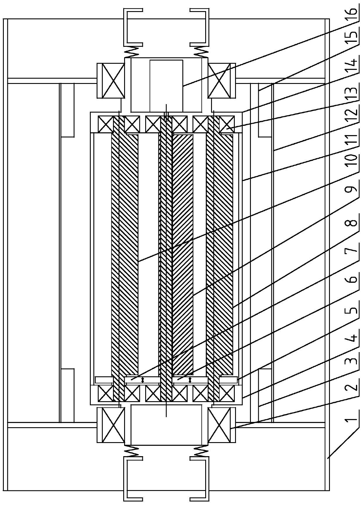
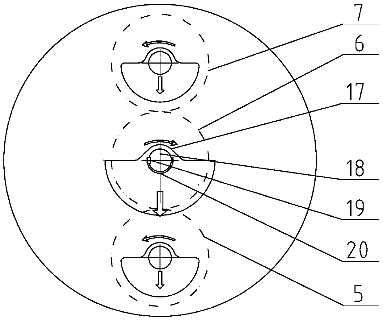
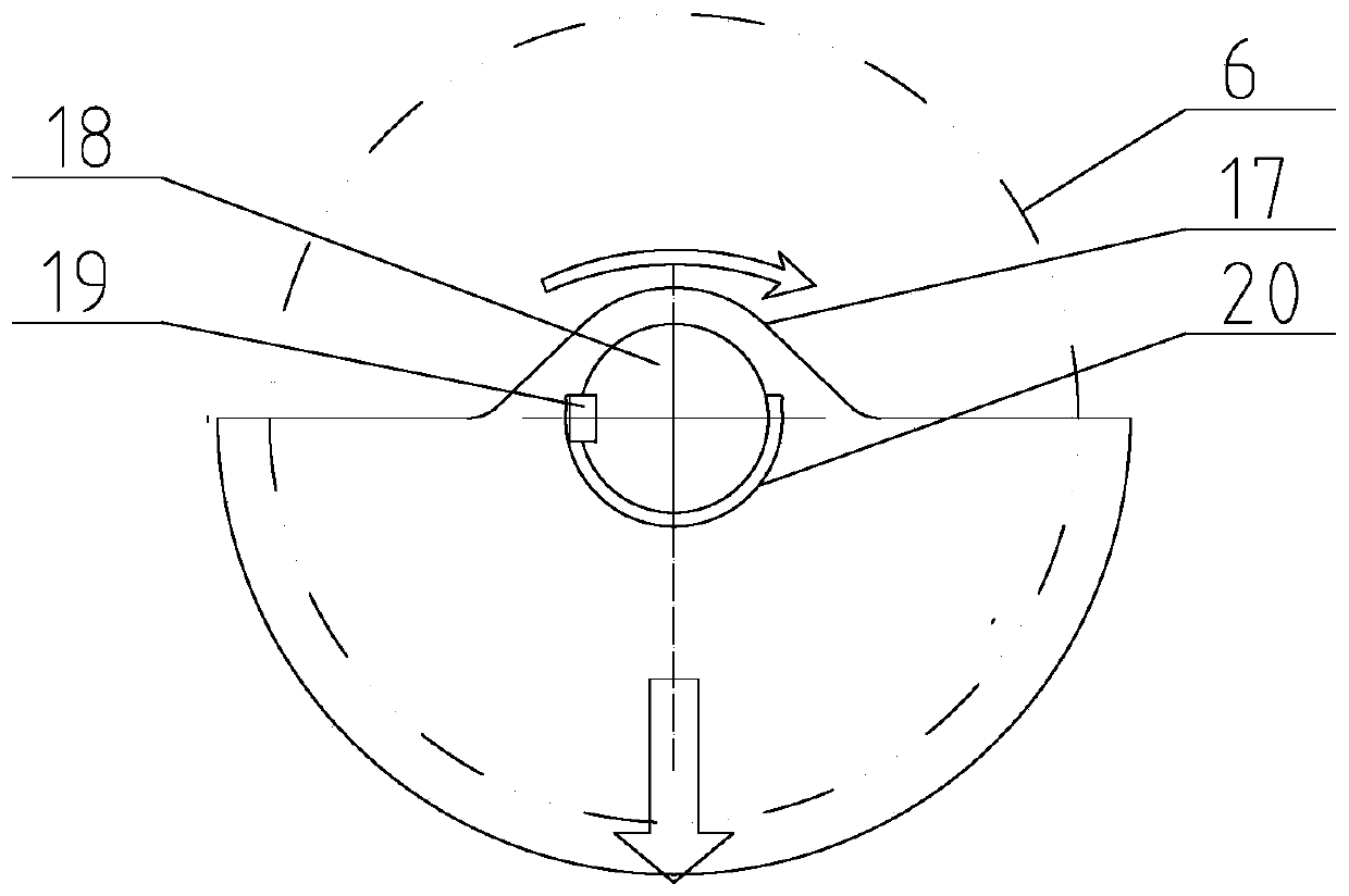
[0049] like Figure 1~2a As shown, a positive and negative switching directional vibration wheel includes a vibration roller 1 and an excitation cylinder 11 arranged inside the vibration roller 1, and the excitation cylinder 11 is provided with three eccentric shafts: a relatively large eccentric shaft Shaft two 9 and two smaller eccentric shafts one 8 and three eccentric shafts 10, the three eccentric shafts are arranged parallel to each other, and the second eccentric shaft 9 is coaxially arranged with the excitation cylinder 11, that is, the second eccentric shaft The axis of 9 coincides with the center of rotation of the excitation cylinder 11...


PUM


Abstract

The invention belongs to the technical field of vibratory road rollers, and in particular relates to a directional vibratory drum capable of switching between rotation and reverse rotation. The directional vibratory drum comprises a vibratory roller and a vibration excitation tube arranged inside the vibratory roller, wherein a second eccentric shaft which is relatively large and a small first eccentric shaft and a third eccentric shaft which are relatively small are arranged in the vibration excitation tube; the three eccentric shafts are arranged parallel to each other; the second eccentricshaft is arranged coaxially with the vibration excitation tube; the first eccentric shaft and the third eccentric shaft are symmetrically arranged on two sides of the second eccentric shaft; the second eccentric shaft is connected to a vibratory motor; the second eccentric shaft separately drives the first eccentric shaft and the third eccentric shaft to perform synchronous reverse movement through a transmission mechanism; and the centrifugal force generated when the second eccentric shaft rotates is equal to the sum of the centrifugal forces generated when the first eccentric shaft and the third eccentric shaft rotate. Through the adjustment of initial positions of the three eccentric shafts and the switching between rotation and reverse rotation of the vibratory motor, the directional vibratory drum can realize directional vibration in two different directions based on a relatively simple structure.

Description

technical field [0001] The invention belongs to the technical field of vibratory road rollers, and in particular relates to a forward and reverse switching directional vibrating wheel. Background technique [0002] The road roller is a construction machine whose main purpose is to increase the compactness of the working medium (earth filling and road pavement mixture). The earliest road rollers were compacted by static force, that is, the static pressure generated by the weight of the road roller was used to force the working medium to be dense. Internal friction between particles is lost, resulting in higher compaction efficiency and better compaction results. Therefore, vibratory rollers have gradually become mainstream. [0003] The vibrating wheel is one of the key components of the vibratory roller. It is not only the working device of the vibratory roller, but also the traveling device of the vibratory roller. [0004] A typical vibrating wheel of a vertical vibrato...

Claims


Application Information

Patent Timeline
Patent Type & Authority Applications(China)
IPC IPC(8): E01C19/28
Inventor 黄方权
Owner 黄方权
Why Eureka
Try Eureka