
Energy recycling device for vehicle

An energy recovery device and vehicle technology, applied in the direction of control devices, auxiliary drive devices, mechanisms for generating mechanical power, etc., can solve the problem of increasing the impact of the mover and the moving mechanical components of the speed increaser, the difficulty of lubrication and cooling of the speed increaser, and the suspension Poor reliability and other issues, to achieve the effect of compact structure, eliminating the need for lubrication and cooling systems, and reducing impact

Active Publication Date: 2019-05-07
CHINA NORTH VEHICLE RES INST
View PDF5 Cites 2 Cited by
  • Summary
  • Abstract
  • Description
  • Claims
  • Application Information

AI Technical Summary

Problems solved by technology

However, due to the slow vibration speed of the wheel, the relative movement speed of the mover (such as permanent magnet) and the stator (such as coil) is slow, the power generation is small, and the power generation efficiency is also low. Add a speed-increasing device or a speed-increasing device in between to increase the relative motion speed of the mover and the stator, but because the vehicle reciprocates up and down, the impact is still very large, and the mover and the mechanical transmission mechanism bear alternating loads, so it is easy to increase the speed of the mover. The impact between the gear and the moving mechanical components of the speed increaser, the suspension reliability is poor, and the service life is low; secondly, because a speed increaser is added to the suspension, the weight increases, and the lubrication and cooling of the speed increaser are difficult

Method used


Image

  • Energy recycling device for vehicle
  • Energy recycling device for vehicle
  • Energy recycling device for vehicle

Examples


Embodiment Construction

[0066] In order to better understand the present invention, the technical solution of the present invention will be further described in detail below in conjunction with the accompanying drawings.

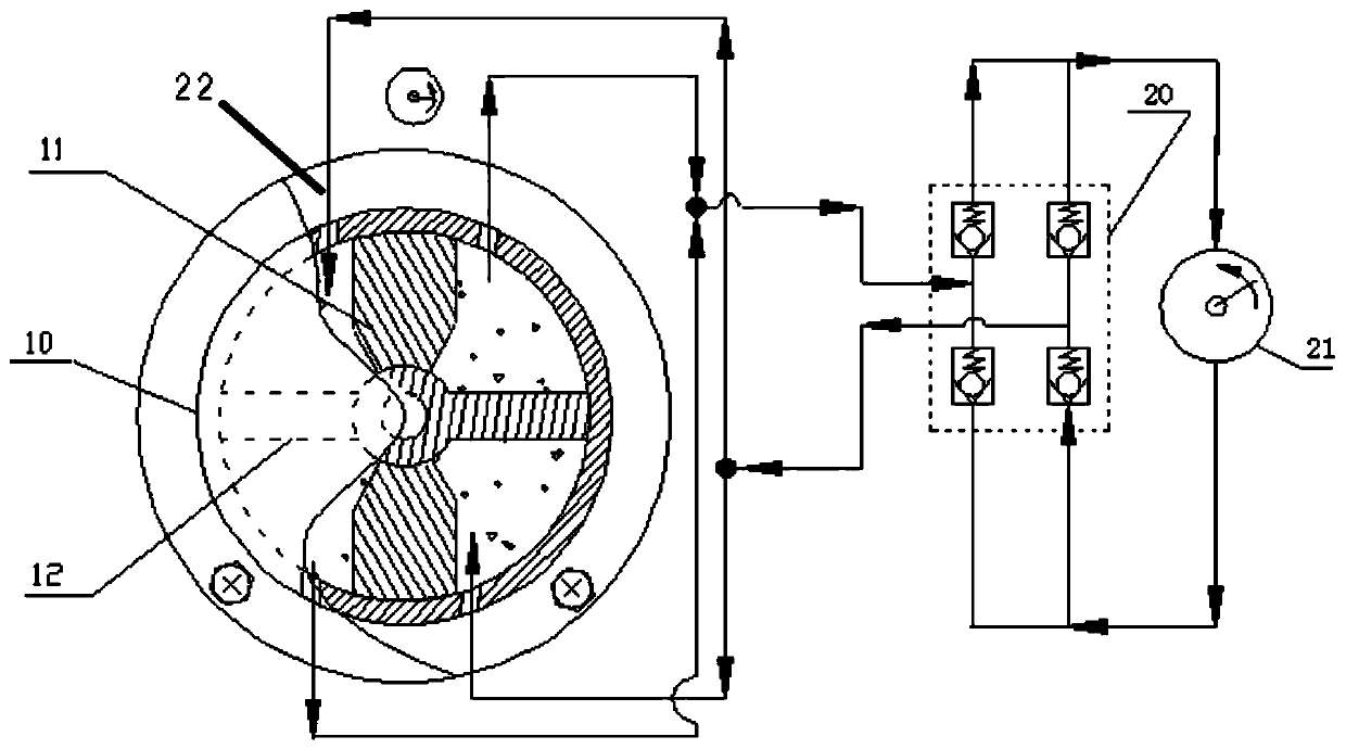
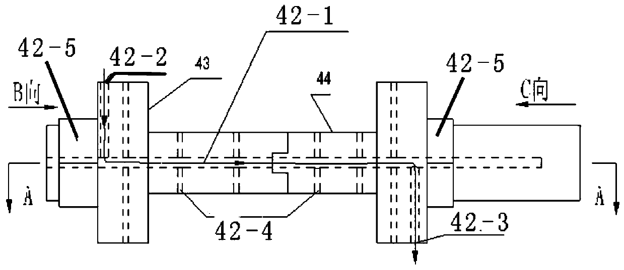
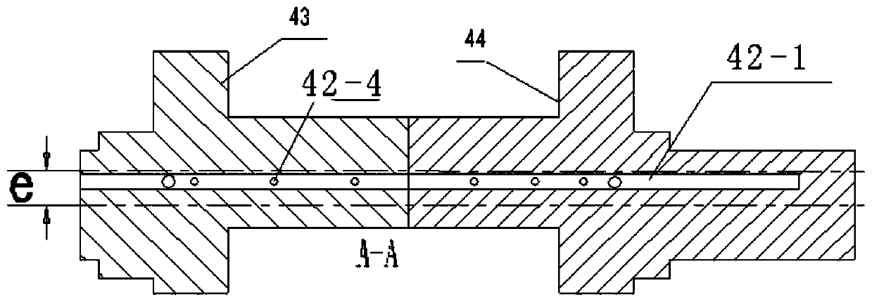
[0067] Such as Figure 1 to Figure 18 As shown, this embodiment provides an energy recovery device for a vehicle, the vehicle includes: a pull arm, a generator and an on-board battery;

[0068] The generator is connected to the vehicle battery;

[0069] The energy recovery device includes: a hydraulic shock absorber 22, a hydraulic commutator 20 and a hydraulic speed increaser 21, and the hydraulic shock absorber 22, the hydraulic commutator 20 and the hydraulic speed increaser 21 are sequentially connected to form a hydraulic drive circuit;

[0070] The hydraulic speed increaser 21 is fixedly connected with the generator;

[0071] The hydraulic shock absorber 22 is fixedly connected to the pull arm;

[0072] The hydraulic shock absorber 22 includes: a throttle hole, a seal and...


PUM


Abstract

The invention discloses an energy recycling device for a vehicle. The vehicle comprises a pulling arm, an electric generator and a vehicle-mounted battery, and the electric generator is connected withthe vehicle-mounted battery. The energy recycling device comprises a hydraulic shock absorber, a hydraulic commutator and a hydraulic speed increaser, and the hydraulic shock absorber, the hydrauliccommutator and the hydraulic speed increaser are sequentially connected to form a hydraulic driving circuit; the hydraulic speed increaser is fixedly connected with the electric generator; the hydraulic shock absorber is fixedly connected with the pulling arm; the hydraulic shock absorber comprises a throttling small hole, a sealing part and a channel hole; the sealing part is arranged in the throttling small hole and used for sealing the throttling small hole; the pulling arm does reciprocating motion to drive shock absorption oil to pass through the channel hole of the hydraulic shock absorber, the shock absorption oil enters the hydraulic speed increaser to drive the electric generator to generate electricity after flowing through the hydraulic commutator to be commutated, and electricity generated by the electric generator is stored in the vehicle-mounted battery; and the shock absorption oil flows into the hydraulic shock absorber through the hydraulic commutator.

Description

technical field [0001] The invention relates to a recovery device, in particular to an energy recovery device for vehicles. Background technique [0002] At present, when the hydraulic shock absorber performs vibration reduction work, energy is dissipated in vain. For this reason, someone utilizes conversion mechanism and electromagnetic device to convert vehicle vibration energy into electric energy. However, due to the slow vibration speed of the wheel, the relative movement speed of the mover (such as permanent magnet) and the stator (such as coil) is slow, the power generation is small, and the power generation efficiency is also low. Add a speed-increasing device or a speed-increasing device in between to increase the relative motion speed of the mover and the stator, but because the vehicle reciprocates up and down, the impact is still very large, and the mover and the mechanical transmission mechanism bear alternating loads, so it is easy to increase the speed of the...

Claims


Application Information

Patent Timeline
Patent Type & Authority Applications(China)
IPC IPC(8): F03G7/08B60G13/14
Inventor 汪国胜李春明雷强顺魏来生
Owner CHINA NORTH VEHICLE RES INST
Learn More