Load-sensitive multi-way valve and hydraulic system

A load-sensing, multi-way valve technology, applied in the direction of fluid pressure actuation system components, fluid pressure actuation devices, servo motor components, etc., can solve the problem that the pressure of the load-sensing pump cannot be unloaded, the Ls pressure fluctuates greatly, and it is easy to generate shocks, etc. problems, to achieve the effect of improving flow control performance, ensuring coordinated actions, and working reliably

Active Publication Date: 2019-05-07
JIANGSU XCMG CONSTR MASCH RES INST LTD
View PDF22 Cites 5 Cited by
  • Summary
  • Abstract
  • Description
  • Claims
  • Application Information

AI Technical Summary

Problems solved by technology

However, when more than three actions are moving at the same time, one action is required to be prioritized, and other actuators are coordinated to move, the load-sensitive multi-way valve before and after the valve cannot meet this functional requirement.
[0008] (2) In the prior art, the pressure of each connection of the load-sensitive multi-way valve behind the valve can only be adjusted individually by setting the secondary overload oil supply valve at the load port. The valve overflows back to the oil tank, causing a large amount of energy loss and system heating
[0009] (3) In the prior art, when the load-sensing multi-way valve is in the middle position, the load-sensing pump works at the minimum swing angle, and the pump outputs a small flow rate. At this time, the pressure cannot be unloaded, causing the pressure to be too high, which may easily cause the engine to stall
[0010] (4) At present, the load feedback pressure signal of the load-sensitive multi-way valve adopts the shuttle valve to screen the highest pressure, and the arrangement of the load feedback pressure signal oil channel on the valve body is complicated, and at the same time, the Ls pressure fluctuates greatly during the reversing process, which is prone to shock

Method used


Image

  • Load-sensitive multi-way valve and hydraulic system

Examples


Embodiment 1

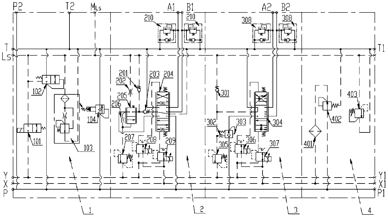
[0055] In some embodiments, such as figure 1 As shown, a load-sensing multi-way valve includes a first joint 1, a tail joint 4, and several post-valve compensation working joints 2 and several pre-valve compensation working joints 3 arranged between the first joint and the tail joint; the first joint 1. A number of post-valve compensation working couplers 2, a number of pre-valve compensation working couplers 3 and a tail coupler 4 are fixedly connected together by double-ended studs. P oil supply oil circuit, X pilot oil supply oil circuit, Y oil drain oil circuit, Ls load feedback oil circuit, T oil return oil circuit run through several post-valve compensation working joints 2 and several pre-valve compensation working joints 3 from the first joint 1 and taillink 4.

[0056] figure 1 Only one post-valve compensation working couplet 2 and one pre-valve compensation working couplet 3 are shown in . In actual application, multiple post-valve compensation working couplets 2 a...


PUM


Abstract

The invention discloses a load-sensitive multi-way valve and a hydraulic system. The load-sensitive multi-way valve comprises a head joint, a tail joint, more than one behind-valve compensation work joint and more than one front-valve compensation work joint; the behind-valve compensation work joints and the front-valve compensation work joints are arranged between the head joint and the tail joint, and the head joint, the tail joint, the behind-valve compensation work joints and the front-valve compensation work joints are fixedly connected; and a P oil supply oil circuit, an X pilot oil supply oil circuit, a Y oil drain oil circuit, a Ls load feedback oil circuit and a T oil return oil circuit pass through the behind-valve compensation work joints, the front-valve compensation work joints and the tail joint from the head joint. According to the load-sensitive multi-way valve integrating the behind-valve compensation work joints and the front-valve compensation work joints, the advantage of front-valve and behind-valve load sensitivity is achieved. The multi-way valve is provided with the behind-valve compensation work joints and the front-valve compensation work joints to achievethe load sensitivity function, the flow control performance is improved, and the host operation controllability is better.

Description

technical field [0001] The invention belongs to the technical field of engineering machinery, and in particular relates to a load sensitive multi-way valve and a hydraulic system. Background technique [0002] The multi-way valve is the control center of the entire hydraulic system and the core component of the hydraulic system. It is located between the pump and the actuator and is used to control the flow and direction of the hydraulic oil, thereby centrally controlling the movement direction and speed of the actuator of the construction machinery. The performance of the multi-way valve directly affects the controllability and comfort of the whole machine system. [0003] In the early days of construction machinery, throttling multi-way valves were widely used, mainly relying on throttling to adjust the flow to the actuator, so the speed regulation characteristics are greatly affected by the load pressure. In order to improve the control performance of multi-way valve, th...

Claims


Application Information

Patent Timeline
Patent Type & Authority Applications(China)
IPC IPC(8): F15B13/02F15B21/00
Inventor 刘灿杰肖刚刘莹莹
Owner JIANGSU XCMG CONSTR MASCH RES INST LTD
Why Eureka
Try Eureka