Magnetic pole gap measuring device and method for circular accelerator

A cyclotron, magnetic pole gap technology, applied in mechanical gap measurement, mechanical thickness measurement, etc., can solve measurement problems, achieve good social benefits, and be suitable for popularization and use.

Inactive Publication Date: 2019-05-07
HEFEI CAS ION MEDICAL & TECHNICAL DEVICES CO LTD
View PDF9 Cites 1 Cited by
  • Summary
  • Abstract
  • Description
  • Claims
  • Application Information

AI Technical Summary

Problems solved by technology

[0003] The purpose of the present invention is to solve the problem that after the magnetic pole is assembled with the iron yoke cover plate and the iron yoke waist, the magnetic pole is inside the accelerator, and the assembled magnetic pole cannot be measured by a laser tracker or other direct measurement methods. In order to solve the problem of the gap between the magnetic poles of the cyclotron, a device and method for measuring the magnetic pole gap of the cyclotron is proposed. The present invention realizes accurate measurement of the magnetic pole gap in the closed state, and the upper and lower magnetic poles squeeze the soldering wire on the measuring tool under the action of gravity. Compression deformation, and then measure the height from the solder wire to the bottom of the tooling with a vernier caliper, so as to obtain the magnetic pole gap; the invention has good social benefits and is suitable for popularization and use

Method used


Image

  • Magnetic pole gap measuring device and method for circular accelerator
  • Magnetic pole gap measuring device and method for circular accelerator

Examples


Embodiment Construction

[0021] The technical solutions of the present invention will be clearly and completely described below in conjunction with the embodiments. Apparently, the described embodiments are only some of the embodiments of the present invention, not all of them. Based on the embodiments of the present invention, all other embodiments obtained by persons of ordinary skill in the art without creative efforts fall within the protection scope of the present invention.

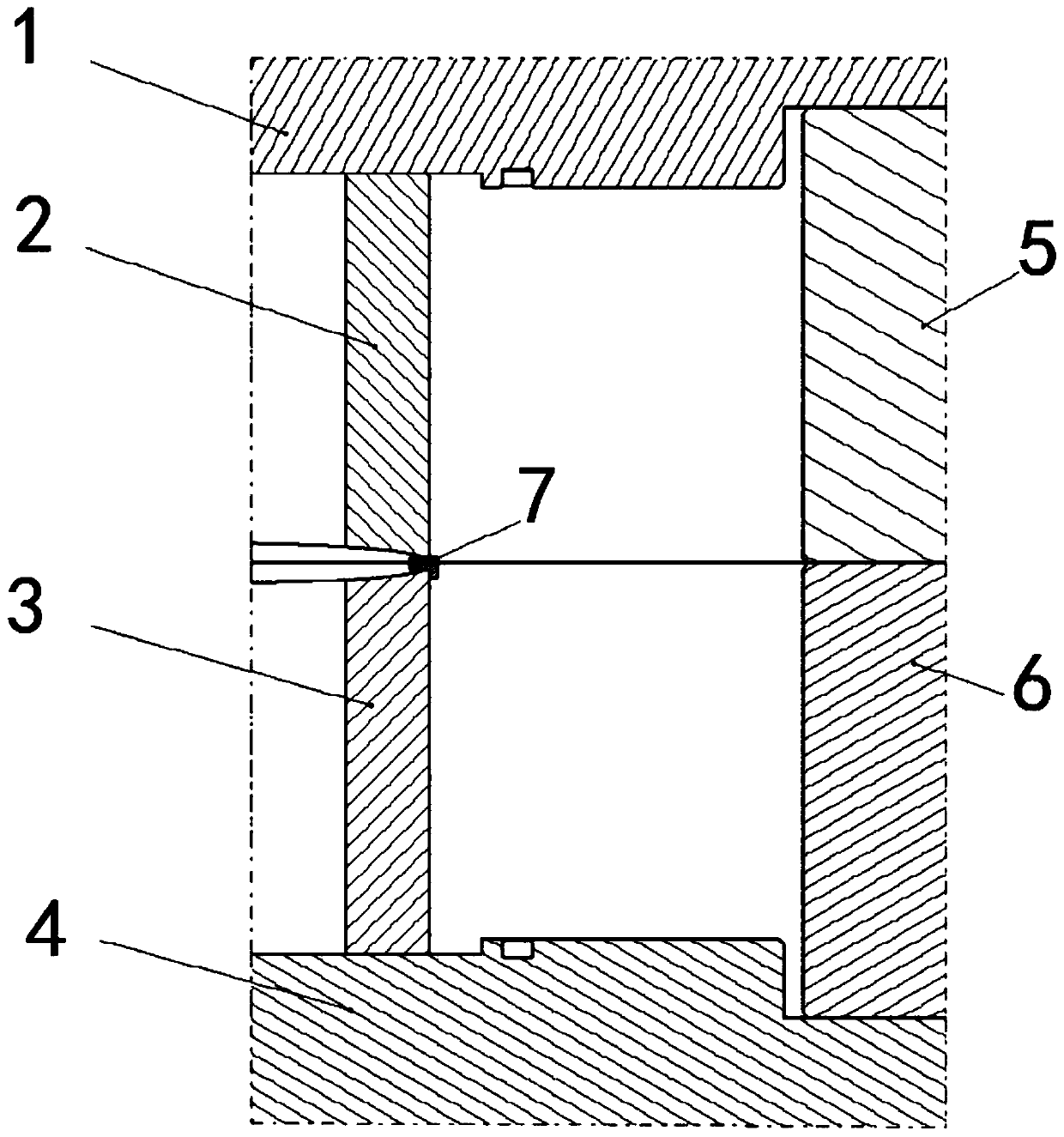
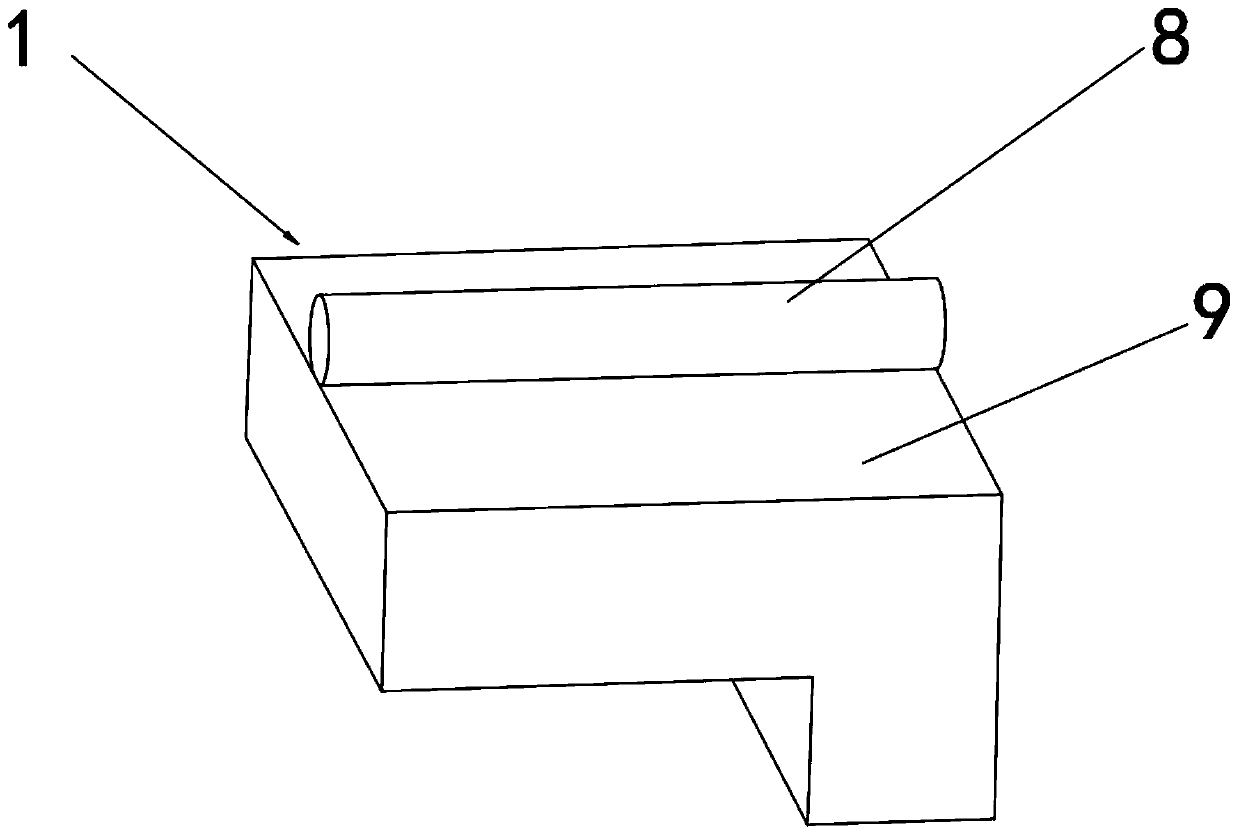
[0022] see Figure 1-2 As shown, a cyclotron magnetic pole gap measurement device includes an upper iron yoke cover plate 1, an upper magnetic pole 2, a lower magnetic pole 3, a lower iron yoke cover plate 4, an upper iron yoke waist 5, a lower iron yoke waist 6 and a magnetic pole The gap measuring tool 7, the upper iron yoke cover 1 and the lower iron yoke cover 4 are respectively arranged horizontally at the upper and lower ends of the device, and the upper magnetic pole 2 is installed under one end of the upper iron yok...


PUM


Abstract

The invention discloses a magnetic pole gap measuring device and method for a circular accelerator. The magnetic pole gap measuring device includes an upper iron yoke cover plate, an upper magnetic pole, a lower magnetic pole, a lower iron yoke cover plate, an upper iron yoke waist, a lower iron yoke waist and a magnetic pole gap measuring tool, the upper iron yoke cover plate and the lower iron yoke cover plate are arranged horizontally at the upper end and the lower end of the magnetic pole gap measuring device correspondingly, and the upper magnetic pole is installed below one end of the upper iron yoke cover plate; and the upper iron yoke waist is vertically arranged at the bottom of the other end of the upper iron yoke cover plate, and the upper magnetic pole and the upper iron yoke cover plate are vertically arranged. The magnetic pole gap measuring device and method for the circular accelerator has the beneficial effects that accurate measurement of the magnetic pole gap in theclosed state is realized, extrusion deformation of a tin soldering wire on the magnetic pole gap measuring tool by the upper magnetic pole and the lower magnetic pole under the action of gravity is conducted, and then by measuring the height of the tin soldering wire to the bottom of the magnetic pole gap measuring tool through a vernier caliper, the magnetic pole gap can be obtained. The magneticpole gap measuring device and method has good social benefits and is suitable for use and popularization.

Description

technical field [0001] The invention relates to a magnetic pole gap measurement method, in particular to a cyclotron magnetic pole gap measurement device and method, and belongs to the technical field of cyclotron magnetic pole gap measurement application in a closed environment. Background technique [0002] With the current rising demand for cancer treatment, proton therapy has become an effective means of treating tumors. Because of the energy distribution characteristics of the Bragg peak of the proton in the material, by controlling the position of the proton Bragg peak, it can effectively kill the lesion while reducing the damage to the surrounding healthy tissue. The accelerator is the core component of the proton therapy device, which can accelerate protons and increase the energy of protons. The magnet system is the main part of the accelerator, especially the magnetic pole parts. The magnetic poles close to the mid-plane are flat at the outer end, and the rest are...

Claims


Application Information

Patent Timeline
IPC IPC(8): G01B5/14G01B5/06
Inventor 丁开忠蔡斌李君君潘结春周鹏艳周健韩务林
Owner HEFEI CAS ION MEDICAL & TECHNICAL DEVICES CO LTD
Why Eureka
Try Eureka