
Intelligent vibration acceleration sensor base

A technology of vibration acceleration and sensor, which is applied in the direction of measuring acceleration, speed/acceleration/shock measurement, speed/acceleration/electric shock meter detailed information, etc. It can solve the problems of cumbersome measurement accuracy and improve inspection efficiency and reduce procurement Cost, installation method and reliable effect

Pending Publication Date: 2019-05-07
中国船舶重工集团公司第七0四研究所
View PDF0 Cites 0 Cited by
  • Summary
  • Abstract
  • Description
  • Claims
  • Application Information

AI Technical Summary

Problems solved by technology

[0012] The present invention is to provide an intelligent vibration acceleration sensor base, which is used to solve technical problems such as cumbersome input of inspection information of the inspection equipment and measurement accuracy of the inspection instrument.

Method used


Image

  • Intelligent vibration acceleration sensor base
  • Intelligent vibration acceleration sensor base
  • Intelligent vibration acceleration sensor base

Examples


Embodiment Construction

[0030] The present invention will be further described below in conjunction with the accompanying drawings and embodiments.

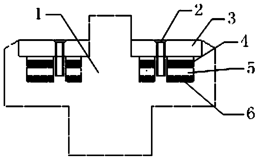
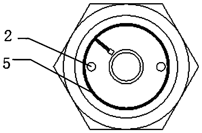
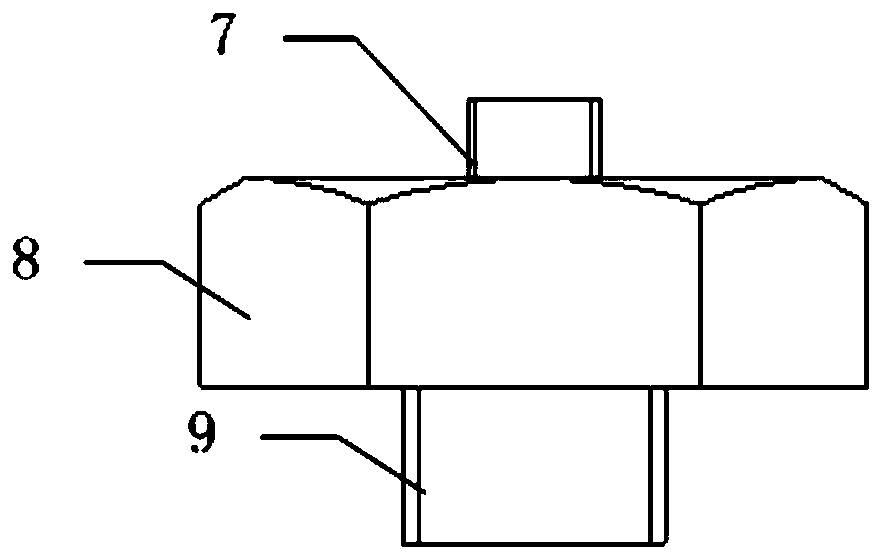
[0031] Such as Figure 1 to Figure 3 As shown, an intelligent vibration acceleration sensor base mainly includes a sensor base block 1, mounting screws 2, ceramic cover plate 3, filling coating 4, and RFID electronic tag module 5. The sensor base block 1 includes its structural main body 8, the upper stud 7 connected with the acceleration sensor and the lower stud 9 connected with the device. The ceramic cover plate 3 is combined with the sensor base block 1 through the mounting screws 2 and the sealant, and is made of ceramic material for the convenience that the radio frequency signal of the electronic label module can be transmitted. The RFID electronic tag module 5 is installed on the bottom of the sensor base block 1 through the bottom insulating gasket 6 , and then sealed and fastened through the filling coating 4 .

[0032] Such as Figure 4 A...


PUM


Abstract

The invention relates to an intelligent vibration acceleration sensor base. The intelligent vibration acceleration sensor base is provided with a sensor base block and one or more radio frequency identification (RFID) electronic tag modules, the RFID electronic tag modules are installed at the bottom of the sensor base block through an insulating gasket at the bottom, the upper parts of the RFID electronic tag modules are connected with the sensor base block in sealing and tightening modes through filling coatings, and the upper part of the sensor base block is connected with a ceramic cover plate in sealing and tightening modes. According to the intelligent vibration acceleration sensor base, on the basis of an acceleration sensor base, RFID electronic tags are arranged through structuralimprovement, and equipment information and measuring point information of theintelligent vibration acceleration sensor base can also be automatically identified while an acceleration sensor is fixed;and compared with online monitoring equipment, the vibration acceleration sensor is not required to be embedded in the position of a measured point, online measurement cables are not required to be arranged, in the way, the purchase cost of front-end sensors is lowered, and the risks of sensor damage and poor accuracy after long-term shelving are further lowered.

Description

technical field [0001] The invention relates to an intelligent vibration acceleration sensor, in particular to a base of the vibration acceleration sensor. Background technique [0002] The vibration acceleration sensor has a wide frequency range of acceleration signals, a large range, high sensitivity, and is easy to install and use. It has been widely used in equipment vibration testing, status monitoring, equipment inspection, fault diagnosis and health management. [0003] The sensor base is generally a transitional mounting seat between the sensor and the side of the device, but it is affected by the specific base structure and installation method. The actual upper limit frequency is not the natural resonant frequency of the acceleration sensor itself, but is subject to the installation resonant frequency. (Installation resonance frequency refers to the resonance frequency when the acceleration sensor is firmly mounted on an object with a finite mass M). Generally, the...

Claims


Application Information

Patent Timeline
IPC IPC(8): G01P15/097G01P1/00G01P1/12
Inventor 符栋梁李国平王强张跃张心玮陶巧伟
Owner 中国船舶重工集团公司第七0四研究所
Learn More