
Information acquisition method and terminal

An acquisition method and terminal technology, applied in the field of communications, can solve the problems of low matching between biometric information and the measured object, low recognition pass rate, poor cleanliness, etc., so as to improve the recognition pass rate, speed up the recognition speed, and reduce the requirements. Effect

Pending Publication Date: 2019-05-07
VIVO MOBILE COMM CO LTD
View PDF4 Cites 0 Cited by
  • Summary
  • Abstract
  • Description
  • Claims
  • Application Information

AI Technical Summary

Problems solved by technology

[0004] Embodiments of the present invention provide an information acquisition method and terminal to solve the problem of low matching between the generated biometric information and the measured object due to the poor cleanliness of the measured object in the existing recognition technology, which in turn leads to a low recognition pass rate. low problem

Method used


Image

  • Information acquisition method and terminal
  • Information acquisition method and terminal
  • Information acquisition method and terminal

Examples


Embodiment approach 1

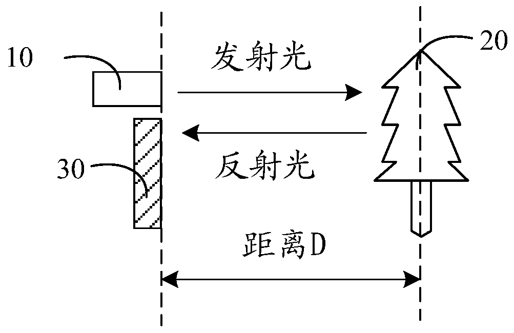
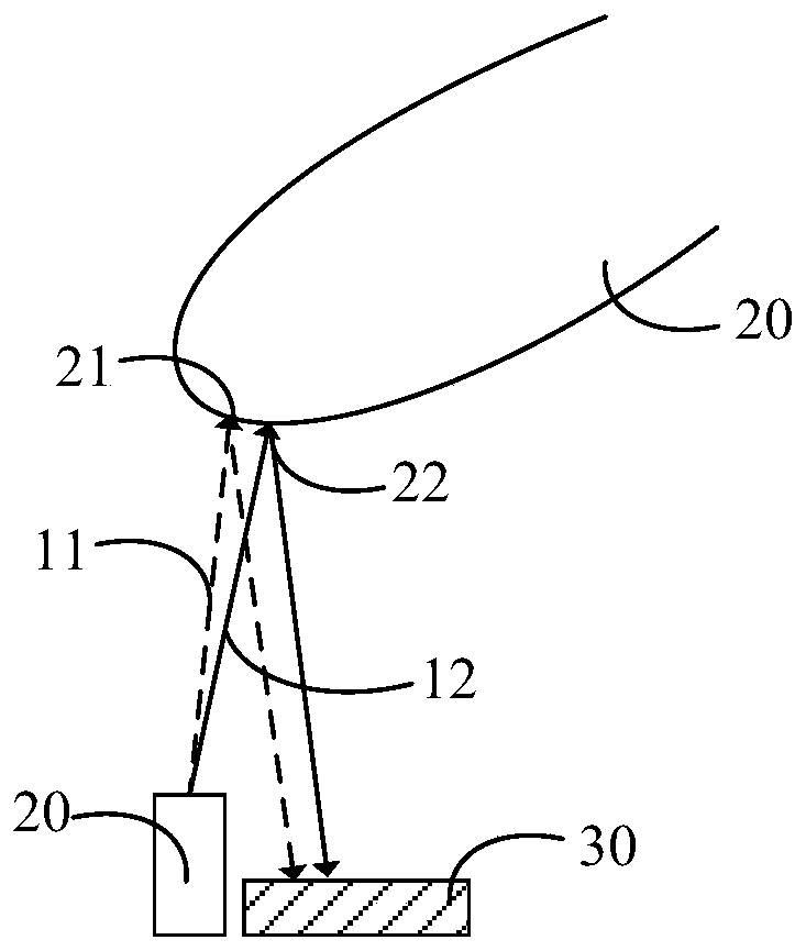
[0049] Optionally, controlling the light emitting unit to emit a light signal, and controlling the TOF sensor to detect the light energy of the light signal reflected by the measured object includes:

[0050] Controlling the light emitting unit to emit a first light signal, and controlling the TOF sensor to detect the first light signal reflected by the object under test at the start moment when the light emitting unit emits the first light signal light energy;

[0051] Controlling the light emitting unit to emit a second light signal, and at the end of the light emitting unit emitting the first light signal, controlling the TOF sensor to detect the second light signal reflected by the object under test. light energy;

[0052] The generating biometric information corresponding to the measured object according to the light energy detected by the TOF sensor includes:

[0053] Biometric information corresponding to the measured object is generated according to the ratio of the ...

Embodiment approach 2

[0064] Optionally, controlling the light emitting unit to emit a light signal, and controlling the TOF sensor to detect the light energy of the light signal reflected by the measured object includes:

[0065] Controlling the light emitting unit to emit a light signal, and at the start moment when the light emitting unit emits the first light signal, controlling the timer to start timing, and controlling the TOF sensor to detect that the light signal is reflected by the measured object light energy;

[0066] The generating biometric information corresponding to the measured object according to the light energy detected by the TOF sensor includes:

[0067] If the TOF sensor detects that the light energy of the light signal reflected by the measured object is greater than the first threshold, the timer is controlled to stop timing, and the duration recorded by the timer is determined;

[0068] According to the duration recorded by the timer, biometric information corresponding t...


PUM


Abstract

The invention provides an information acquisition method and a terminal. The terminal comprises a light emission unit and a flight time sensor. The method comprises the following steps: controlling the light emitting unit to emit a light signal, and controlling the time-of-flight sensor to detect the light energy of the light signal reflected by the detected object; And generating biological characteristic information corresponding to the detected object according to the light energy detected by the time-of-flight sensor. Visibly, the biological characteristic information is obtained based onthe time-of-flight distance measurement; the requirement for the cleanliness of the detected object can be lowered, so that under the condition that the cleanliness of the detected object is poor,; compared with the prior art, the matching degree of the generated biological characteristic information and the detected object is high, the recognition speed can be increased when recognition is carried out through the biological characteristic information, and the recognition passing rate is increased.

Description

technical field [0001] The embodiments of the present invention relate to the field of communication technologies, and in particular, to an information acquisition method and a terminal. Background technique [0002] With the rapid development of communication technology, the functions of terminals are becoming more and more abundant, and the issue of privacy has become an issue that people are more and more concerned about. In order to better improve security and protect privacy, recognition technologies such as fingerprint recognition and face recognition are more and more widely used in terminals. [0003] However, the existing recognition technology has the disadvantage of low matching degree between the generated biometric information and the measured object due to the poor cleanliness of the measured object, which in turn leads to a low recognition pass rate. Contents of the invention [0004] Embodiments of the present invention provide an information acquisition m...

Claims


Application Information

Patent Timeline
Patent Type & Authority Applications(China)
IPC IPC(8): G06F21/32G06K9/00G06K9/20
Inventor 王睿李文锦
Owner VIVO MOBILE COMM CO LTD
Learn More